Documentation
The mesh for a Pedestrian Wind Comfort analysis (PWC) is quite different than for the Finite-Volume-based fluid dynamics analysis types on SimScale, as it is based on the lattice-Boltzmann method (LBM). Here a cartesian background mesh is generated, which is composed only of cube elements that are not necessarily aligned with the geometry of the buildings or the terrain.
To take into account the exact geometry, there exists a sub-grid model that accounts for the interfaces between the geometry and the fluid domains.
The big advantage of the lattice-Boltzmann method is that the grid size is not bound by the small details of the geometry and that it is a lot more robust with respect to inaccuracies in the CAD model such as small holes, overlaps, or intersections.
The sizing for the background mesh for the PWC analysis is highly automated and targeted towards the specific use case, thus it works best for model sizes of 1 – 10 \(km^2\) and a region of interest radius of 200 \(m\) – 500 \(m\).
Note
If you are specifically looking for mesh guidelines for the City of London, they can be found here.
The main logic of the mesh algorithm is as follows:
| Fineness | Number of Refinements Levels | Number of Cells per Disc Diameter |
|---|---|---|
| Very Coarse | 4 | 16 |
| Coarse | 5 | 16 |
| Moderate | 5 | 24 |
| Fine | 6 | 16 |
| Very Fine | 6 | 24 |
$$ Maximum\ Cell\ Size = \frac{ Disc\ Diameter}{Number\ of\ Cells\ Per\ Disc\ Diameter} $$
$$ Minimum\ Cell\ Size = \frac{ Maximum\ Cell\ Size}{2^{Number\ of\ Refinement\ Levels}} $$
The following example (Table 2) shows maximum and minimum cell sizes per disc radius, using automatic meshing process.
| ROI Radius \([m]\) | Very Coarse max / min \([m]\) | Coarse max / min \([m]\) | Moderate max / min \([m]\) | Fine max / min \([m]\) | Very Fine max / min \([m]\) |
|---|---|---|---|---|---|
| 100 | 12.5 / 0.8 | 12.5 / 0.4 | 8.3 / 0.3 | 12.5 / 0.2 | 8.3 / 0.1 |
| 200 | 25.0 / 1.6 | 25.0 / 0.8 | 16.7 / 0.5 | 25.0 / 0.4 | 16.7 / 0.3 |
| 300 | 37.5 / 2.3 | 37.5 / 1.2 | 25.0 / 0.8 | 37.5 / 0.6 | 25.0 / 0.4 |
| 400 | 50 / 3.1 | 50.0 / 1.6 | 33.3 / 1.0 | 50.0 / 0.8 | 33.3 / 0.5 |
Based on the desired fineness level one can approximate the mesh size as follows (Table 3):
| Fineness | Very Coarse | Coarse | Moderate | Fine | Very Fine |
|---|---|---|---|---|---|
| Relative minimum size | 1 | 1/2 | 1/3 | 1/4 | 1/6 |
| Minimum size per 100 \(m\) radius | 0.78 | 0.39 | 0.26 | 0.20 | 0.13 |
| Relative cell count approximation | 1 | 2 | 4 | 8 | 16 |
| Ratio \(D/h\) | Very Coarse | Coarse | Moderate | Fine | Very Fine |
| \(D/h\) = 2 | 10e6 | 12e6 | 25e6 | 45e6 | 100e6 |
| \(D/h\) = 4 | 4e6 | 5e6 | 12e6 | 18e6 | 45e6 |
| \(D/h\) = 10 | 1.5e6 | 3e6 | 7e6 | 10e6 | 20e6 |
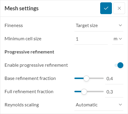
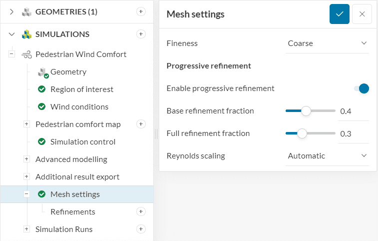
The Reynolds scaling factor can be accessed under Mesh settings. The Reynolds number is defined as \(Re= \frac{UL}{\nu} \) where \(L\) is the reference length, \(U\) is the velocity, and \(\nu \) is the kinematic viscosity of the fluid. When a scaling factor is applied, instead of sizing the geometry down, the viscosity is increased to ensure that the Reynolds number is reduced to the correct scaling.
In most urban scale flows, an Automatic Reynolds scaling is recommended to ensure accurate results. Like wind tunnel models, we use Reynolds scaling assuming that bluff bodies (block-like buildings) and high Reynolds numbers are present. This enables the concept of similarity of large Reynolds numbers. When both these conditions are met, automatic scaling is valid. Automatic Reynolds scaling helps you get accurate results, cheaper without extensive expertise.
Advanced users operating outside the typical assumptions of urban scales are welcome to use manual scaling, however, they should consider the impacts on wall modeling and rely on their expertise. A scale of 1 represents full scale, and 1/250 or 1/400 would represent a typical wind tunnel scale. Automatic values in SimScale are typically in the order of 1/10.
Progressive refinement is a feature that allows users to speed up their pedestrian wind comfort studies by utilizing coarser meshes in towards the beginning of the simulation and transitioning into finer meshes as the simulation goes beyond a certain percentage of progress. This feature enables to drastically reduce the run times (typically between 35% and 45%) without impacting the results significantly.
To understand the benefit of progressive refinements, it is important to recognize that PWC studies consist of transient simulations that oftentimes involve large flow domains and meshes.
The initial condition for velocity of a PWC simulation is zero velocity globally. As such, the main objective towards the beginning of a PWC run is to develop the flow field. By using a coarser mesh in this stage, you can develop the flow while spending less computational resources.
The setup of a progressive refinement requires two parameters:
Important
It is a recommendation that the user waits at least 5% of simulation progress after the final mesh starts being used for the impact of the full refinement to develop. In practice, this means that the Full refinement fraction should be at least 0.05 greater than the Fraction from end values in the transient and statistical averaging outputs:
Figure 3: Fraction from end definition within additional result export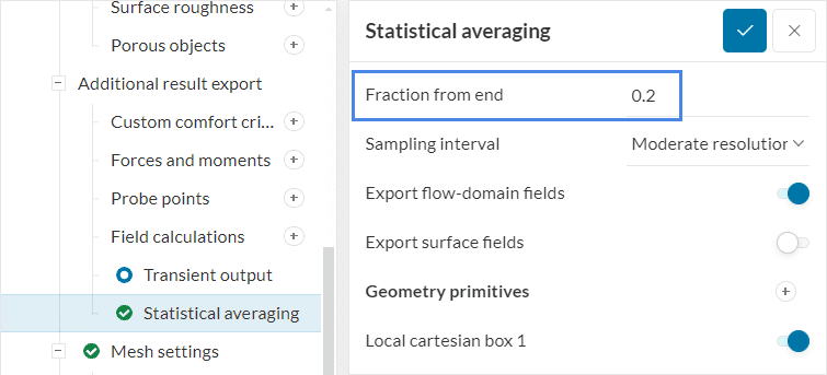
Sometimes it is required to put additional focus on specific regions like entrance areas, narrow street canyons between high rise buildings, complex terrain or vegetation, and local mesh refinements in these regions are desired.
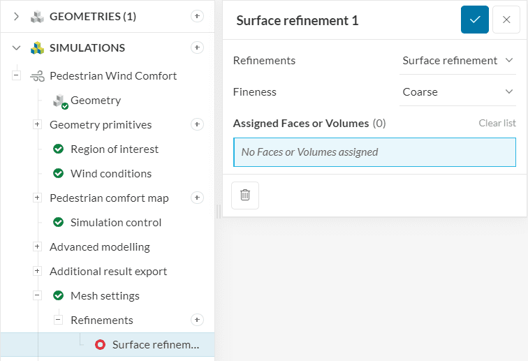
In such cases, either a Surface refinement or a Region refinement can be added.
A surface refinement is best suited for cases where a specific building or a set of its surfaces or solids should be refined.
The fineness can be defined analogously to the global mesh sizing from Very coarse to Very fine. Also, in the same way, as it is done for the global mesh sizing inside the region of interest, the surface refinement will result in a layer of 4-6 cells of the smallest cell size and gradually increasing with a larger distance from the surface.
In case a region between two buildings or a specific open area that is of interest would need to be refined, a region refinement would be best suited. In order to locate the region where the mesh should be refined, a geometry primitive of type sphere or box can be created using the ‘+’ button and assigned by activating the slider in front of it.
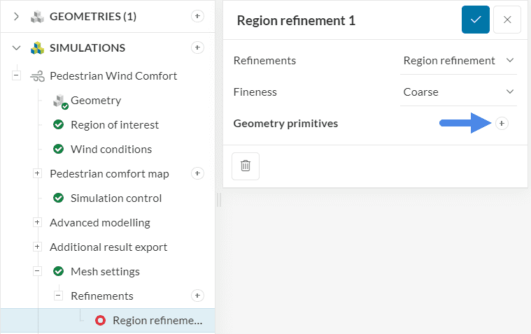
The sizing for the region of interest is the same as for the global sizing and the surface refinement, but in contrast to them, the smallest cell size will be kept throughout the whole assigned domain.
Note
As a general recommendation, a local refinement that is more than one level finer than the global fineness is to be avoided as it will reduce the overall simulation efficiency. In such cases it is rather recommended to also reduce the global mesh size and limit the size difference to one level.
References
Last updated: December 13th, 2024
We appreciate and value your feedback.
What's Next
Starting a PWC Run and Accessing Run Informationpart of: Pedestrian Wind Comfort Analysis
Sign up for SimScale
and start simulating now