Documentation
Joule heating is the physical effect by which the pass of current through an electrical conductor produces thermal energy. This thermal energy is then evidenced through a rise in the conductor material temperature, thus the term “heating”. One can see Joule heating as a transformation between “electrical energy” and “thermal energy”, following the energy conservation principle.
The heating effect was first studied and characterized by the then-to-be-famous amateur scientist James Prescott Joule, around the year 1840. As a manager in his family’s brewery, Joule set to investigate if the then recently invented electrical motor could be more efficient than the steam engines in use at the process, in terms of cost (it turned out they weren’t, electrical energy had to be produced from zinc batteries). This led him to conduct a series of experiments on the production, transfer, and use of energy and mechanical work that ultimately led to the first law of thermodynamics (the SI unit of energy was named Joule in his honor)\(^1\).
Among those experiments was the study of the relation between the electrical current that flows through a conductor and the rise in its temperature. The experiment consisted of a wire submerged in water and connected to the terminals of a battery. When the circuit was engaged, a rise in the water temperature could be measured. The analysis of the recorded data led to the original form of the relation now known as Joule’s first law, that “the heat per unit time developed in the wire is proportional to the resistance of the wire and to the square of the current”. In mathematical form:
$$\frac {H}{t} = I^2R \tag{1}$$
where:
The modern most common way of writing the relation given by the law involves the generated power \(P\) instead of the heat and time:
$$\frac {H}{t} = P = I^2R \tag{2}$$
It was known then, thanks to Joule, that heat is generated in a conductor through the effect of an electric current, but how?
Electric current is no more than the flow movement of electrons, caused by what is called an “electromotive force”: a difference in electric potential through two points in a material, which tends to cause the electrons in the material to move. Note that it “tends” to cause the movement, because this movement depends on many factors: the availability of free electrons to be moved, the “easiness” with which the electrons can move, and the magnitude of the electromotive force. This effect is summarized in Ohm’s law:
$$I = \frac {V}{R} \tag {3}$$
It states that the electric current \(I\), which is the amount of moving electric charge per unit of time, flowing through the conductor is proportional to the difference in electric potential at its ends \(V\) and inversely proportional to the resistance of the conductor material \(R\).
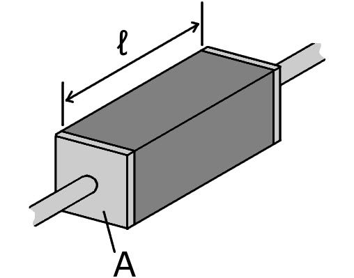
This resistance then represents the opposition of the conductor to the flow of current: the higher the resistance, the harder it is for the current to flow. Experiments have shown that resistance depends not only on the material of the conductor but also on its geometry (length and cross-section area). Hence, an intrinsic property of the material is stated, the resistivity, such that the resistance (\(R\)) of the conductor can be calculated as:
$$R = \frac {\rho l}{A} \tag {4}$$
where:
It can be seen, then, that all materials present an opposition to the flow of current, to varying degrees: some materials are better at conducting an electric current, and others are worse at it (but better at isolating the electric current, which is also very useful because the current can be blocked, for example for safety reasons). There is even the possibility of materials with zero (or almost zero) resistance to current flow, the so-called “superconductors”. A table of resistivity values for many materials can be found at this link\(^3\).
But how all of this relates to Joule heating? Looking at Joule’s law we can see that, for a given current, the higher the resistance of the conductor, the more heat is produced. Simply put, the harder it is to move electrons through the conductor, the more work is spent at moving them, work that is directly converted to heat in the material. And “directly” means that no energy is lost in this process to other forms. Indeed, this is one of the few processes in nature that have this characteristic.
Given that we have an electrical conductor (might be a wire, bar or plate) of length \(l\), cross-sectional area \(A\), that is made of a material with resistivity \(\rho\), one can calculate its electrical resistance with equation 4, that was posted above.
$$R = \frac {\rho\ l}{A} \tag {4}$$
If the conductor is then subjected to an electrical potential difference \(V\) at its ends terminals (in direct current), a current \(I\) will flow through it, according to Ohm’s law, from equation 3:
$$I = \frac {V}{R} \tag {3}$$
The power \(P\) dissipated in the conductor and transformed to heat is given by Joule’s law. Remembering the second equation from this article:
$$P = I^2R \tag{2}$$
An amount of heat \(Q\) is then built up in the conductor after a time \(t\):
$$Q=Pt \tag {5}$$
The rate at which the temperature rises in the conductor can then be determined by the relation:
$$T = \frac {Q}{cm} \tag {6}$$
Where \(c\) is the specific heat of the material and \(m\) is the total mass of the conductor.
Here it is assumed that all geometrical and material parameters are constant across the length of the conductor and that a consistent system of units is used for quantities.
For the case of alternating current, the above relations would give the power dissipated in an instant of time, and the built-up heat relation is no longer valid. To fix that, the root mean square\(^4\) of the power, current and voltage are used, so that now we use the relations:
$$I_{RMS}=V_{RMS}R \tag {7}$$
$$P = P_{RMS}=I_{RMS}^2R \tag {8}$$
And the rest of the calculation remains equal.
Joule heating of materials is used extensively in many applications at home, transportation, and industry products. To name a few:
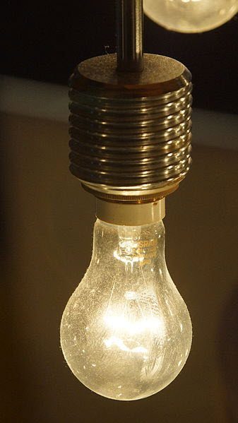
Incandescent light bulbs, where a filament is heated with electricity and light is emitted.
Resistance ovens, where the heat from the conductor is put to use through thermal radiation and convection. For example:
Resistance direct heating, where the heat from the conductor is put to use through direct heat flow. Examples:
Induction heating, where variable magnetic fields induce currents to flow in a material, which generates the Joule effect. Examples:
One important aspect to discuss when talking about the applications of electric heating is energy efficiency. As was stated earlier, the conversion from electrical energy to heat in the conductor material process generates no loss. This means that this process is 100% energy efficient. Although, the same cannot be stated for the way the heat from the conductor is put to use. Whether it is through conduction, convection, radiation, or incandescence, electric heat applications tend to be terribly inefficient because much of the heat is wasted in the surroundings, not in the beneficial application.
This means that the ratio of electrical power consumed to the ratio of useful power is usually small, with the main consequence being negative environmental impact through the waste of energy. For example, take a look at this comparison\(^6\), where it is shown that a LED light bulb can consume about five times less power for the same amount of light emitted. The environmental conscience has led to replacing many of the inefficient applications of electrical heating in favor of more efficient technology, such as incandescent lighting for LEDs, or electric stoves, ovens, and heaters for natural gas.
Become a SimScale member!
Heat sources in SimScale are treated as Power sources. All three modes of heat transfer, i.e., conduction, convection, and radiation can be simulated. Join SimScale today and experience cloud-based simulation like no other.
References
Last updated: November 20th, 2023
We appreciate and value your feedback.
What's Next
What is Heat Flux?Sign up for SimScale
and start simulating now