Pedestrian wind comfort analysis in SimScale is based upon the Lattice Boltzmann Solver by Pacefish®\(^1\) and therefore has few geometry requirements in terms of quality, and by that, generally speaking, open geometry, overlapping, and coinciding geometry is ok. However, it is also highly automated, streamlined, and tuned specifically for wind comfort based upon validation projects such as the AIJ cases, best practices from industry in both CFD and wind tunnel methodology, and guidelines and standards. Therefore, to get the most out of the solver, a few considerations need to be given about the tested geometry.
For an overview of all CAD related topics in the context of a PWC simulation, the reader can refer to our documentation here.
Orientation
SimScale’s PWC analysis type requires some basic orientation rules which most tools comply with by default. However, if you are creating geometry from scratch in software that is often used for 3D modeling rather than building or environment orientated it is important to consider these.
The geometry should have the Z+ direction as the up orientation, i.e. Z-axis points to the sky. Also, although not strictly required, the PWC analysis type uses the Y-axis by default to orientate to North, this can be corrected in the platform, but usually, geometries are also created with this in mind.
Sizing and Regions
Geometry should be uploaded in real physical sizing, i.e. scaled-down models should not be uploaded. The default unit is meters, and therefore, when and if exporting STL geometry, you should ensure that this unit is used in the model beforehand.
If you use layers in CAD modeling, delete them before uploading the model into the platform. Otherwise, the features modeled with and without layers can be uploaded as separate parts. Learn more.
You can also select units when uploading STL’s to the SimScale platform. This can be done by matching the unit in the CAD and the SimScale platform, but care should be taken to get this right.
Cell sizing is currently done using reference sizing based upon the building of interest and the building maximum height. Therefore, it is recommended that a region of interest no more than 400 \(m\) is used, to approach the target resolution of 0.5-1 \(m\) when meshing. Click below to learn more about mesh settings in PWC analysis.
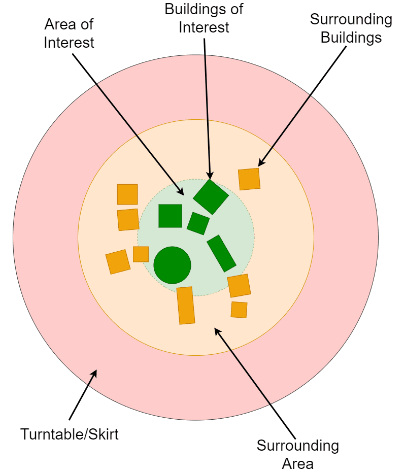
The region of interest should include, in most use cases, the newly proposed building or buildings and the region in which their presence or design might affect the pedestrian’s comfort. The area of interest should include your main buildings of interest and surrounding buildings and can be detailed if you need it.
The surrounding region is likely to affect the aerodynamics significantly in the region of interest so it is advised that the surrounding buildings are present but do not need to have any detail, they can be block representations. Beyond that, the buildings and obstacles will be modeled using a standard wind profile, correcting the exposure to the terrain (ranging from open terrain to the city center).
The PWC analysis type is capable of dealing with geometry intersecting the bounding box, therefore if the bounding box representing the fluid domain limits has geometry outsides of its bounds it will not be included in the solution.
City of London Guidelines
There may be specific restrictions regarding the geometry in use for wind comfort analysis based on the location. Here you can find a set of standard guidelines for the geometry and the mesh when analyzing pedestrian wind comfort in the City of London.
Centering the Model at Origin
When uploading CAD models to the SimScale platform for the purpose of running a PWC simulation, it is recommended to have these models in an STL (.stl) type format. For more information on how to export STL formats in Rhino, kindly refer to the following documentations:
Having mentioned that, usually when dealing with 3D city models there is a very high chance that the components of the model are represented by geo-referenced data. This means, when exporting the model as an STL, the base coordinates (which are based on the geo-referenced data) would be quite large. Generally, we would like to avoid geo-referenced models for the following reason:
“Rhino scales the resolution of the STL export to the size of the model versus the origin.”
This means that Rhino export would break the model and create coarse 3D geometry. To better understand this let’s take a look at the following example, where a 3D model from an area in the city of Bristol is exported using Rhino at two different locations of the center of the model.
In Figure 2, the image on the left shows the STL model exported with center on (0,0,0) while the other image shows the STL model when exported with center coordinates at (5000 \(km\), 5000 \(km\), 0). It can be clearly seen that the model with very far coordinates from the origin had been represented in a much coarser sense which reduces the overall quality of the model due to the reason explained above.
Therefore, it is recommended to ensure that the models are centered at the origin. This would also ease the overall interaction with your model when setting up the simulation parameters.
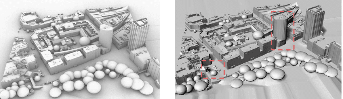
Left: Model centered at (0,0,0); Right: Model centered at (5000 \(km\), 5000 \(km\), 0)
Geometry and Automatic Mesh Sizing Insights
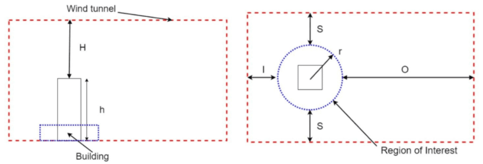
This part will mainly address the question of how the highest structure in the city model affects the overall mesh size. In a PWC simulation, the wind tunnel dimensions (\(H, S, I, O\)) are directly proportional to the maximum height of the model, see Figure 3.
Therefore, it is recommended to analyze the model and identify structures that have no considerable effect on the wind flow pattern. Removing such structures would reduce the computational domain size and in return saves time and cost. For example, a moderate wind tunnel size would be scaled with the following proportions:
$$ H, S, I = 3h $$
$$O = 9h$$
An example that was based on a case from one of our customers, is the presence of a flag inside the 3D model. The flag itself serves no purpose and has a negligible effect on the wind flow pattern due to its small dimension, the only effect it brings is an increase in the size of the computational domain due to a larger \(h\) dimension.
Important
Please be aware that a large building, even if not in the region of interest is relevant and important to keep as it influences the wind flow pattern in its wake.
Related Articles
Our Knowledge Base articles have a great collection of articles associated with CAD issues in PWC analysis. Explore them now!
References


