Validation Case: Mean Age of Air in a Room
The mean age of air in a room validation case belongs to fluid dynamics. This case aims to validate the following parameter:
- The local mean age of air using the SimScale Field function
In this project, the local mean age of air (LMA) within a room is calculated. The SimScale results are compared to the experimental results reported by Martin et. al\(^1\).
Geometry
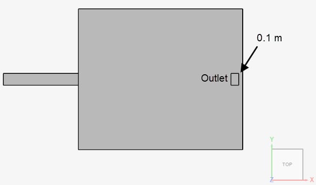
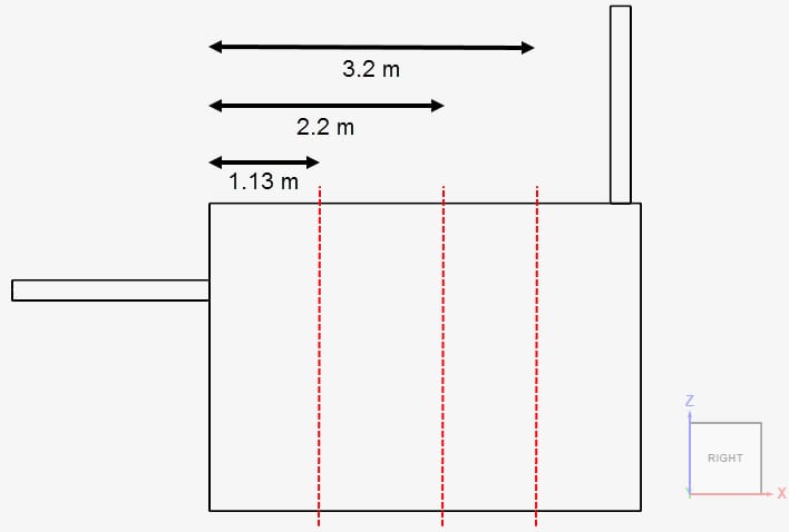
The geometry consists of a rectangular room with one inlet and one outlet, as in Figure 1:

The center points of the inlet and outlet are placed at y = 1.8 meters. Details of the room dimensions are provided in Table 1:
| Part | Length in x-direction \([m]\) | Length in y-direction \([m]\) | Length in z-direction \([m]\) |
| Inlet | 1.92 | 0.30 | 0.20 |
| Outlet | 0.20 | 0.30 | 1.92 |
| Room | 4.20 | 3.60 | 3.00 |
In the study by Martin et. Al \(^1\), the outlet is described to be “on the ceiling, close to the east wall (opposite to the air supply)”, however, no exact placement is given. Based on the description and the schematics of the experimental setup, a gap of 0.1 meters is assumed between the outlet and the wall opposite to the air supply:
Note
By extruding the inlet and outlet sufficiently, we can allow the flow field to develop in these sections. In this case study, the inlet and outlet are extruded by a length equal to 8 times their hydraulic diameter \(D_h\).
$$D_h = \frac {4A}{P} \tag{1}$$
In the formula above, \(A\) is the cross-section area and \(P\) is the wetted perimeter. In our case, the hydraulic diameter for the inlet and outlet is 0.24 meters.
Analysis Type and Mesh
Tool Type: OpenFOAM®
Analysis Type: Incompressible
Turbulence Model: k-omega SST
Mesh and Element Types: This validation case uses a total of 3 meshes to perform a mesh independence study. All meshes were created in SimScale with the Standard mesher algorithm. In Table 2, an overview of them is presented:
| Mesh | Mesh Type | Cells | Element Type |
| Coarse | Standard | 192199 | 3D tetrahedral/hexahedral |
| Moderate | Standard | 538610 | 3D tetrahedral/hexahedral |
| Fine | Standard | 2009591 | 3D tetrahedral/hexahedral |
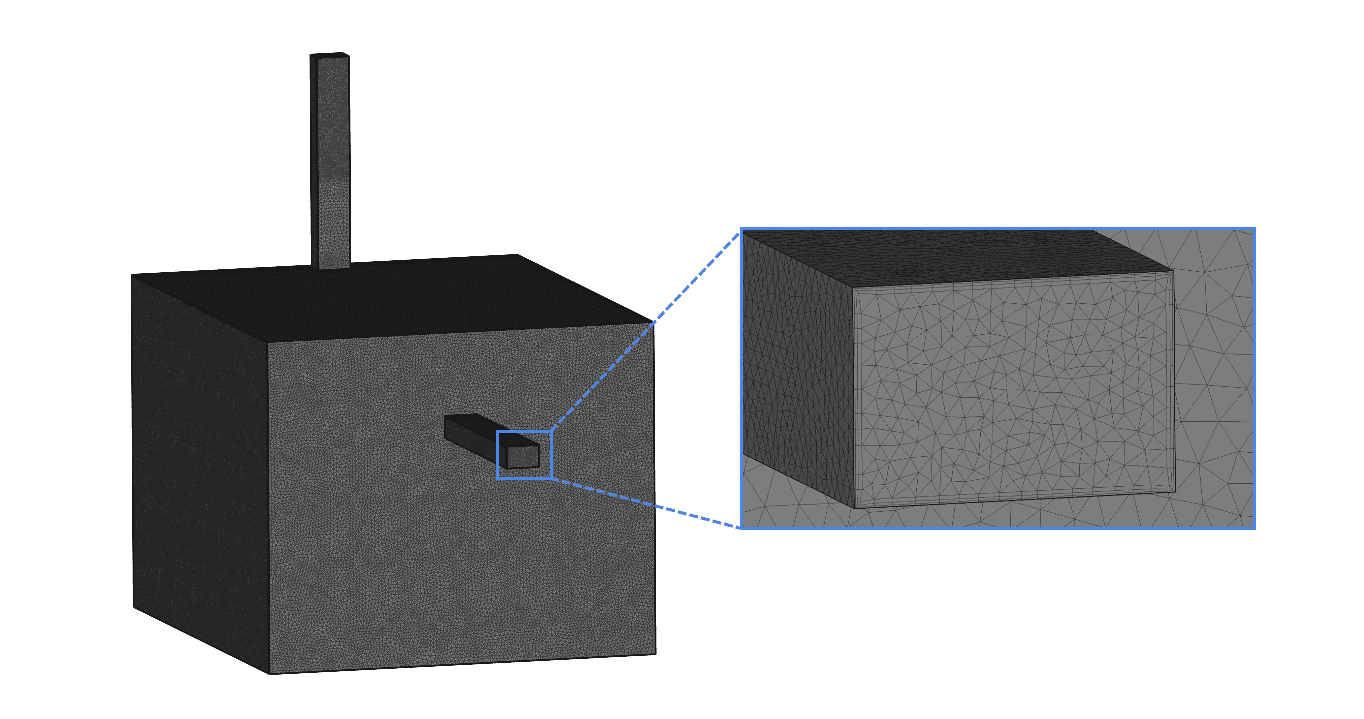
Figure 3 highlights the discretization of the inlet, obtained with the fine standard mesh.
Simulation Setup
Material:
- Air
- Viscosity model: Newtonian
- \((\nu)\) Kinematic viscosity: 1.5295e-5 \(m^2/s\)
- \((\rho)\) Density: 1.196 \(kg/m^3\)
Boundary Conditions:
Figure 4 shows the assignment of the boundary conditions and the corresponding surfaces:
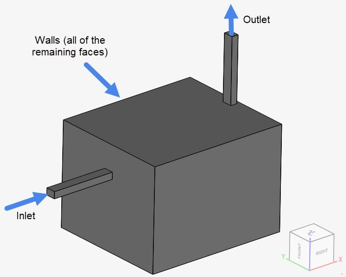
The exact configuration of the boundary conditions is given in the table below:
| Boundary | Boundary Type | Velocity \([m/s]\) | Pressure \([Pa]\) |
| Inlet | Velocity Inlet | 1.68 in the x-direction | Zero gradient |
| Outlet | Pressure Outlet | Zero Gradient | Fixed at 0 |
| Walls | Automatic Wall | No-Slip | Zero gradient |
Model:
- \((Sc_{t})\) Turb. Schmidt number = 1
- Diffusion coefficients = 1e-9 \(m^2/s\)
Note
The diffusion coefficient is purposedly set to a small number. The objective is to prevent the scalar from spreading in the domain via diffusion effects, which would reduce the accuracy of the local mean age of air.
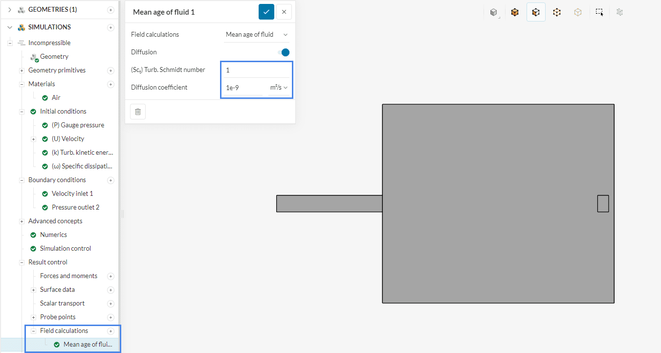
Mean age of air calculation
To track the LMA within the room the in-built SimScale field function is used. To activate this feature extend Result control and create a new ‘Mean age of fluid’ field function by clicking on the plus icon. The diffusion coefficients and the turbulent Schmidt number are set as described before.
Mean age of Fluid Field Function
You can find out moe information about the Mean age of Fluid Field Function here.
Experimental Results
In the experimental tests, Martin et. al\(^1\) first filled the test room with tracer gas and waited to obtain an even distribution. Afterward, fresh air is released at the inlet, which causes the tracer gas concentration to decay.
A series of gas monitors are used to measure how the concentration of the tracer gas evolves with time. The resulting LMA is obtained by calculating the area under the concentration versus time curve.
Note
The theoretical value for the mean age of fluid at the outlet is given by Equation 2:
$$Mean\ age\ of\ fluid = \frac {V}{Q} \tag{2}$$
Where \(V\) is the volume of the test environment and \(Q\) is the volumetric flow rate at the inlet. Using the data from the experimental setup in the equation above, we obtain 450 seconds.
Result Comparison
The numerical simulation results for the LMA are compared with experimental data presented by Martin et. al\(^1\). The authors use a dimensionless form of the LMA to present their results. In the present validation case, the same methodology is used:
$$\overline{\theta} = \frac{\theta}{V/Q} \tag{3}$$
Where:
- \(\overline{\theta}\) is the local mean age of air (dimensionless)
- \(\theta\) is the local mean age of air, in seconds.
- \(V\) is the volume of the passive scalar source, in \(m^3\)
- \(Q\) is the volumetric flow rate at the inlet, in \(m^3/s\)
In addition, the results by Martin et. al \(^1\) are adjusted so that the dimensionless LMA of 1 is corresponding to an LMA of 538 seconds. The values obtained by SimScale have been adjusted accordingly. A comparison of the dimensionless LMA obtained experimentally and with SimScale is presented. The results are assessed on a series of points over three lines, placed on the symmetry plane of the geometry (y = 1.8 meters). The lines are distant 1.13 \(m\), 2.2 \(m\), and 3.2 \(m\) from the inlet, and the points are spread on each line with a distance of 0.1 meters. The placement of the lines can be seen below:
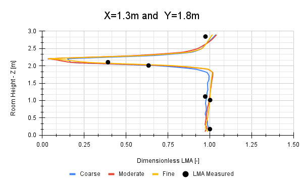
To perform a mesh independence study, the results from the three meshes created in SimScale were compared. The results for all three meshes were found to be mesh independent. Figure 7 shows the results over the line located 1.13 meters away from the inlet.
In the remaining figures, you will find the comparison between the experimental data and the fine mesh results:
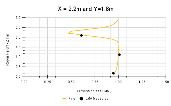
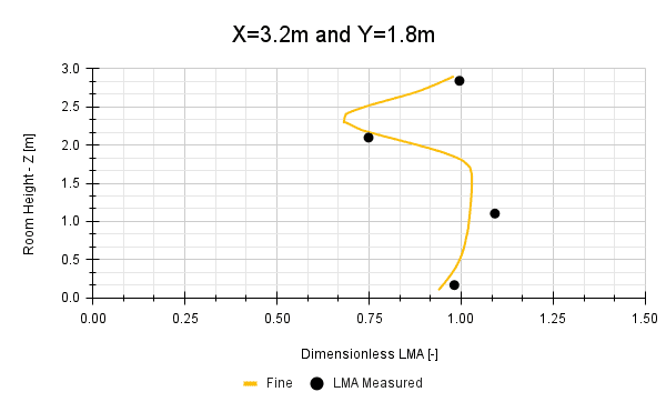
In all cases, the SimScale results show the same trends and range as the experimental values obtained by Martin et. al\(^1\).
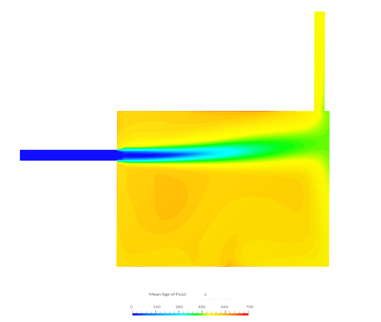
The figure below shows the mean age of fluid on the symmetry plane of the geometry. The fresh air coming from the inlet quickly mixes with the old air in the room. The mean age of air at the outlet for the fine mesh was found to be 451.8 seconds.
Last updated: January 3rd, 2023
Did this article solve your issue?
How can we do better?
We appreciate and value your feedback.


