Documentation
This LED cooling validation case, for high power LED packaging with one heat sink, aims of to validate the following parameters:
The simulation results of SimScale were compared to the theoretical results presented in [Adam]\(^1\).
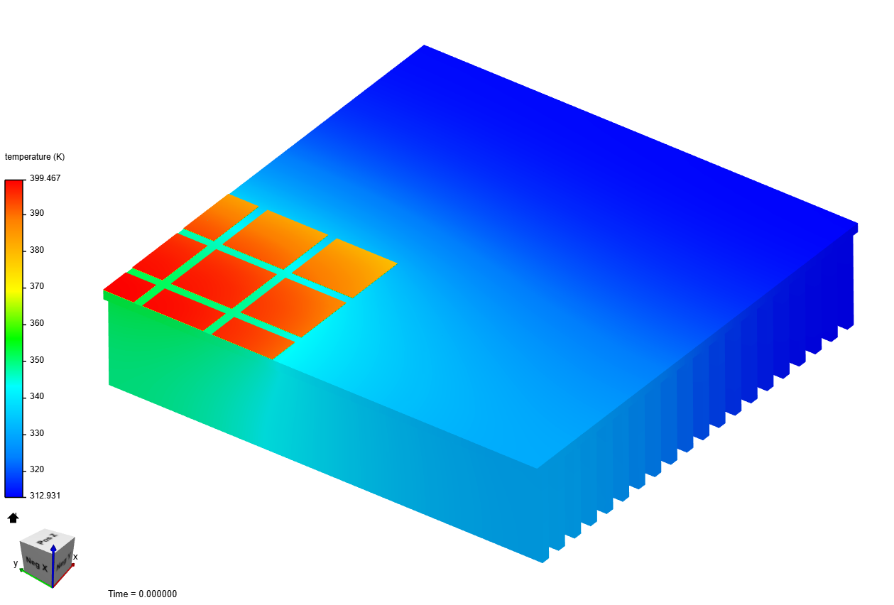
The typical geometry used for the case is as follows:
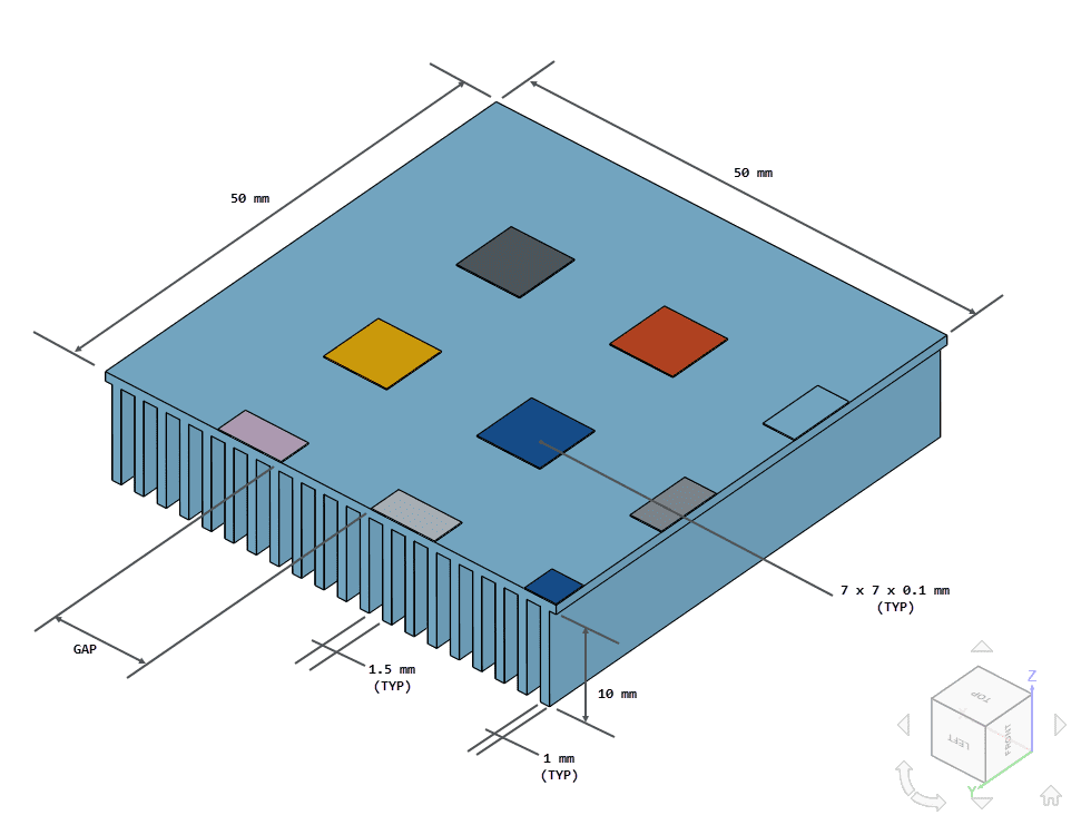
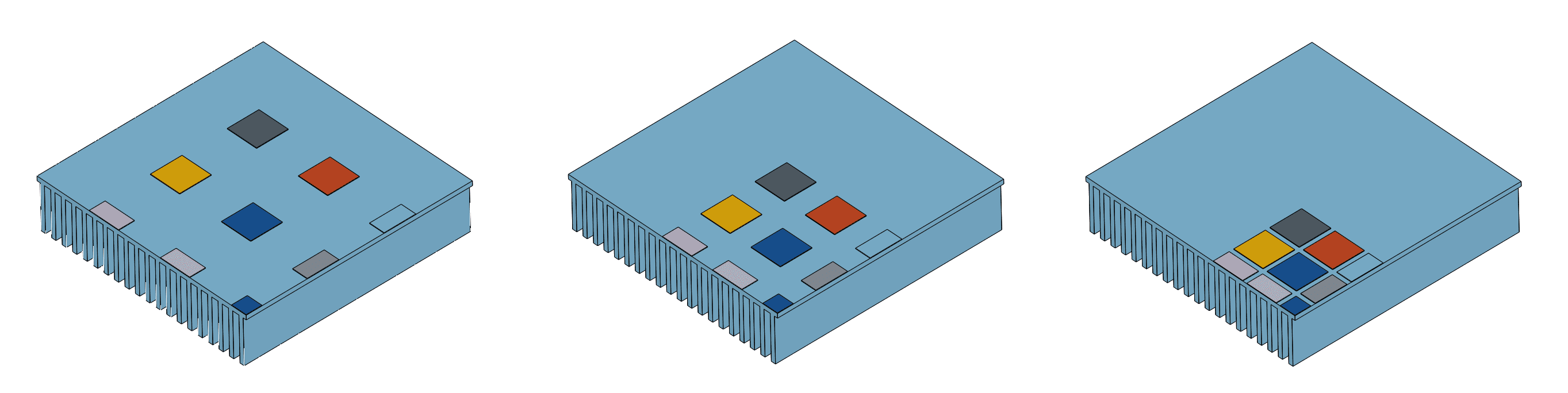
It represents a heat sink of dimensions 100 x 100 \(mm\) with 25 LEDs attached through Thermal Interface Material (TIM) patches of dimensions 7 x 7 x 0.1 \(mm\). Only one-quarter of the geometry is modeled to leverage the symmetry. Gaps of 10, 5, and 1 \(mm\) between LEDs were tested, with each model shown below for comparison:
Tool Type: Code Aster
Analysis Type: Heat transfer, linear, steady-state.
Mesh and Element Types:
| Case | Gap \([mm]\) | Mesh Type | Number of Nodes | Element Type |
|---|---|---|---|---|
| A | 10 | 1st order tetrahedral | 828917 | Standard |
| B | 5 | 1st order tetrahedral | 824569 | Standard |
| C | 1 | 1st order tetrahedral | 824369 | Standard |
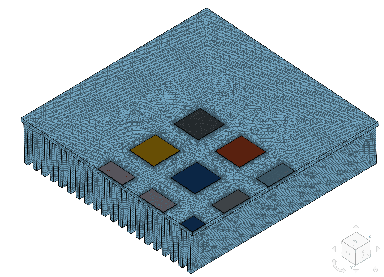
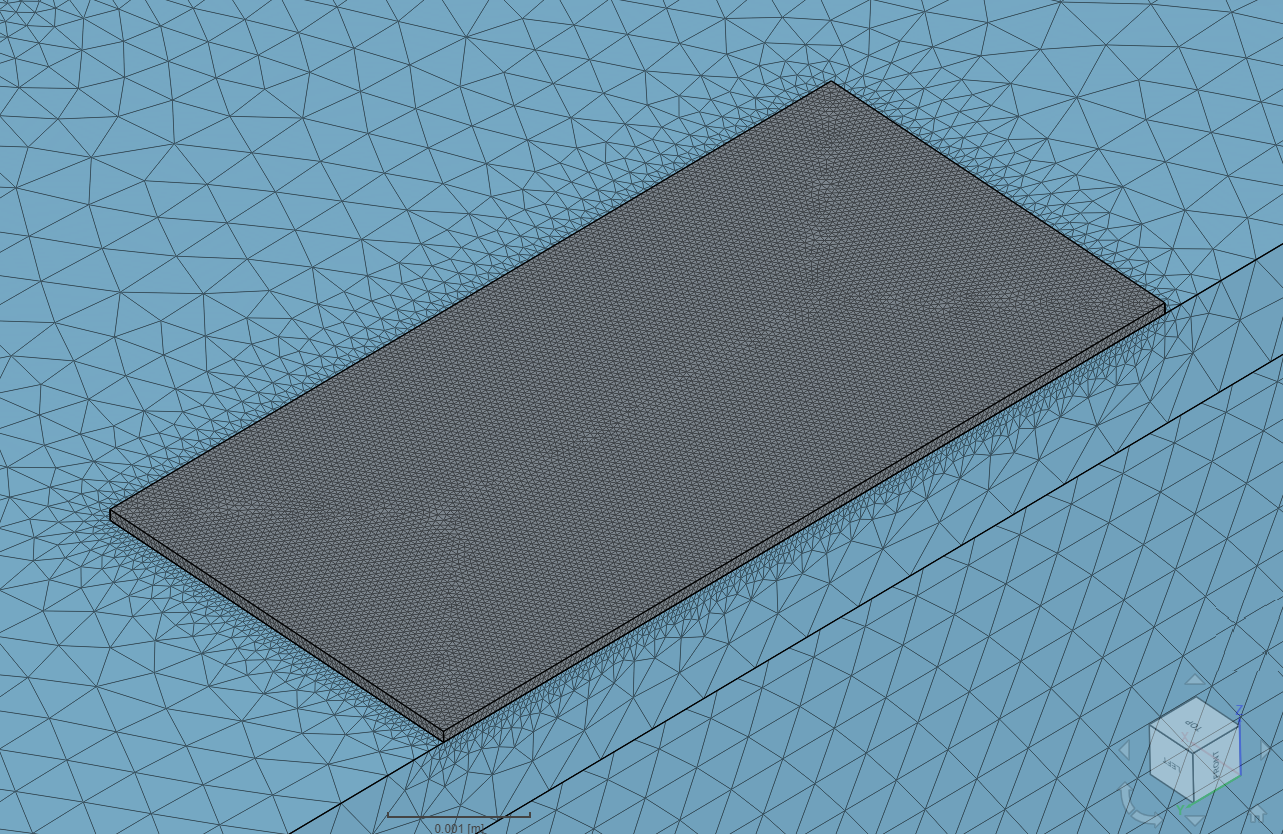
The meshes were computed using the Tet-dominant algorithm with manual mesh sizing and local refinements for the TIM regions. The goal was to keep 2 elements across the thickness of the thin-walled parts, like the heat sink fins and TIM patches.
Material:
The thermal conductivity of the TIM was computed to achieve a total resistance of 9 \(K/W\), according to [INFINEON]\(^2\) with the relation:
$$ \kappa = \frac{t}{RA} $$
Where:
Boundary Conditions:
The following table relates the simulation runs for each case and the combinations of applied boundary conditions:
| Run | Load 1 \([W]\) | Load 3 \([W]\) | Load 5 \([W]\) | Convective flux 10 \([\frac{W}{m^2K}]\) | Convective flux 25 \([\frac{W}{m^2K}]\) | Convective flux 50 \([\frac{W}{m^2K}]\) | Convective flux 75 \([\frac{W}{m^2K}]\) | Convective flux 100 \([\frac{W}{m^2K}]\) |
|---|---|---|---|---|---|---|---|---|
| 1 | X | X | ||||||
| 2 | X | X | ||||||
| 3 | X | X | ||||||
| 4 | X | X | ||||||
| 5 | X | X | ||||||
| 6 | X | X | ||||||
| 7 | X | X | ||||||
| 8 | X | X | ||||||
| 9 | X | X | ||||||
| 10 | X | X | ||||||
| 11 | X | X | ||||||
| 12 | X | X | ||||||
| 13 | X | X | ||||||
| 14 | X | X |
The reference solution is of the analytical type, as presented in [ADAM]\(^1\). It is given in terms of the temperature at the center point as a function of the thermal load and convection coefficients.
Comparison of temperature at the mid point is shown for each case:
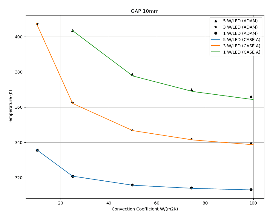
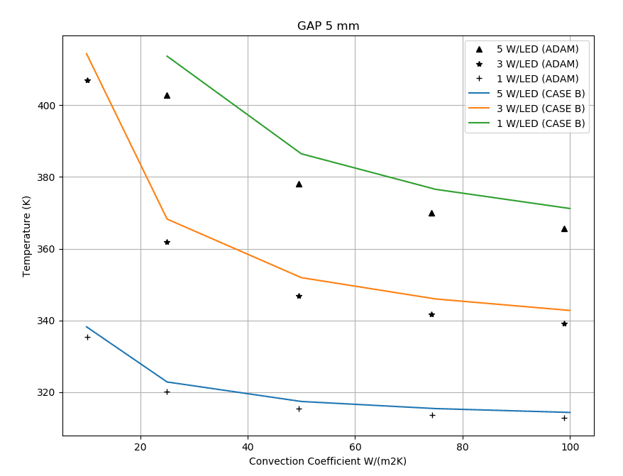
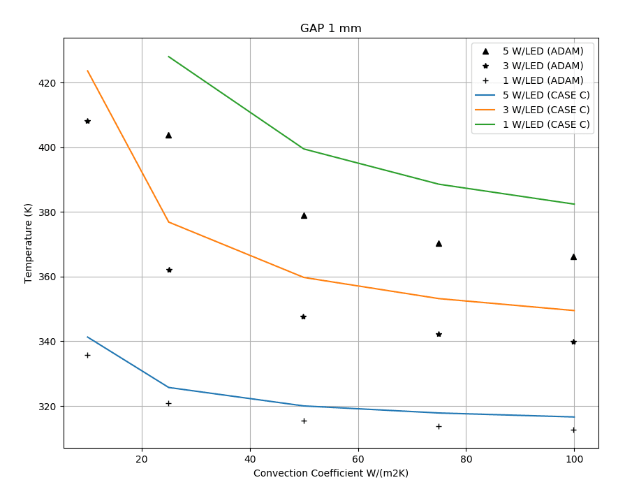
The deviation of the results with respect to [ADAM]\(^1\) in the cases of gap 5 mm and 1 mm can be attributed to a non-uniform temperature distribution at the base of the fins:
Tutorial: Thermal Analysis of a Differential Casing
References
Note
If you still encounter problems validating you simulation, then please post the issue on our forum or contact us.
Last updated: March 25th, 2026
We appreciate and value your feedback.
Sign up for SimScale
and start simulating now


