What is Structural Analysis?
In the field of solid mechanics, structural analysis is the analysis of the response of a structure and its behavior under certain loading conditions. A structure or an assembly may consist of several sub-components. The goal of structural engineers is to analyze all the sub-components but also the structure as a whole. This can be achieved by typically trying to answer the following question:
“Is it going to withstand the loading, or is it going to fail?”
Structural Analysis Basic Notions
Stress, Strain, and Material Behavior
Stress and strain are two really important quantities when it comes to structural analysis.
In a solid, stress (σ) is defined as the internal force (F) within the material that opposes any external loading and runs through any given cross-section (A):
$$\sigma = \frac{F}{A}$$
Any solid under stress will experience deformation. Strain (ε) is a dimensionless quantity that quantifies the relative deformation of materials under stress. Strain is expressed as:
$$\epsilon = \frac{dL}{L}$$
where L is the undeformed length of the solid element and dL is its relative deformation.
Deriving the stresses and strains of a given component is the major goal of structural analysis. However, there are other equally important quantities and analysis types. Typical examples are natural frequencies and mode shapes, vibration responses, buckling, fracture/crack propagation, and material fatigue.
The relationship between stress and strain is:
$$\epsilon = \frac{\sigma}{E}$$
where E is a characteristic material constant known as modulus of elasticity, elastic modulus, or simply Young’s modulus. This property was named after the British scientist Thomas Young.
It is a mechanical property of linear elastic solid materials which quantifies how rigid/stiff a material is. Young’s modulus is often expressed in pressure/stress units (Pa or psi).
Talking about materials, it’s worth mentioning the stress-strain curve. In engineering structural analysis, the most commonly encountered materials are ductile. A part made of a ductile material is able to withstand excessive strains before failure. Figure 1 demonstrates a typical stress-strain curve of ductile materials.
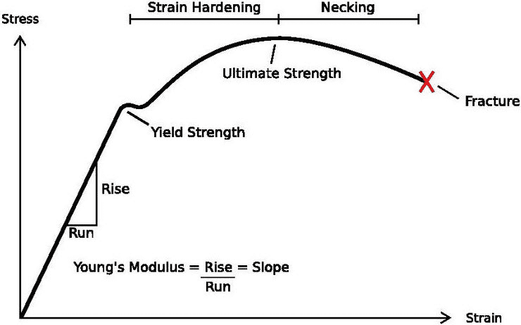
The stress-strain curve is unique for any material and is typically determined through physical testing. There are several types of tests, for example, tensile, compression, and bending tests which lead to material characterization. The stress-strain curve provides engineers and designers with important information about material limits and the risk of failure.
Willing to learn more about stresses and strains and the various stress-strain relationships based on different material types? Then make sure to read our article on the Stress-Strain curve.
Factor of Safety and Allowable Stress
During the design process of a component or a structure, the structural analyst has to ensure that the designed model will withstand all sorts of loads that it is going to experience throughout its designated lifetime. This very much depends on the material properties and the stress-strain characteristic curve that comes with it. There are two main concerns when it comes to material strength:
- What is the limit stress after which a material will experience large and remaining deformation (plastic deformations)? – Yield Strength.
- What is the material strength, which describes the maximum stress that a material can take before it fails? – Ultimate Strength.
The designer must ensure that the developed stresses will never surpass the Ultimate and/or Yield Strength of their product. Of course, the maximum allowable stress should be somewhat lower than these two limits. The reason for that is to account for uncertainties or unpredicted extreme loading conditions. Thus, maximum allowable stress and, in turn, a factor of safety (FoS) of the design can be defined.
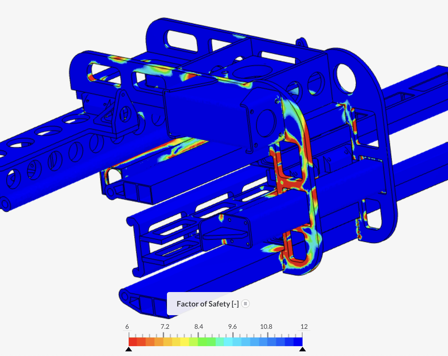
Structural analysis helps to ensure that safety-critical equipment has high safety factors to account for unexpected loading regimes.
$$FoS=\frac{\text{max. allowable stress}}{\text{max. working stress}}$$
Solution Methods
In the case of a simple, statically determinate problem, the reaction and internal forces, which are important for structural analysis, are calculated employing simple statics. This case is really straightforward since the number of unknowns typically equals the number of equations to maintain equilibrium. This is the simplest example of structural analysis.
However, there are cases where the number of unknowns exceeds the number of equilibrium equations. That could be the case of a propped cantilever beam, for instance. This is now a statically indeterminate problem, and we should use alternative methods to solve it.
Virtual Work, Energy, and Matrix Methods
There are three main methods of structural analysis:
- Virtual work methods: The principle of virtual work or the virtual force method is one of the very first and most powerful methods. It is efficient for the analysis of statically in-determinate problems and can extend beyond the linear elastic material range.
- Energy methods: The energy methods (based on strain energy) are more general and can provide estimated solutions to complex problems. These methods are particularly useful when exact solutions do not exist or are difficult to obtain.
- Matrix methods: The advancement of computers and numerical computations led to the development of computer-based techniques. The flexibility and stiffness methods belong to this category.
Work and energy methods oftentimes can be solved by hand and are generally good for smaller and simpler components. Matrix methods are quite useful in modern structural engineering where there is a need for analyzing larger assemblies (i.e. aircraft). A subcategory, or in other words, the evolution of the matrix methods, is the finite element method (FEM).
The FEM is particularly good for continuum structures representing real-life models. Make sure to read our article about Finite Element Analysis. This will help you understand how FEM works in practical engineering problems.
Of course, talking about structural analysis solution methods could be endless. It is hard to cover all these details in a single article. One academic textbook I possess and I like to retrieve when looking for more information about structural problems is Aircraft Structures for Engineering Students by T.H.G. Megson. [2]
Modern Structural Analysis
With the development of modern computing, engineers and designers implement structural analysis methods more regularly in their daily jobs. They can use dedicated FEA or structural analysis software to reduce the number of physical prototypes required for testing at the component or assembly level. A computer now handles all the sets of mathematical equations and unknowns. This allows engineers to perform speedy computations and reach design decisions faster.
Cloud-Native Structural Analysis
New technology has flattened the barriers. Now structural analysis simulation is truly accessible through any web browser leveraging the power of cloud computing. Engineers can run multiple designs in parallel and post-process simulation results online. SimScale provides structural analysis software right in your web browser. SimScale makes engineering simulation easily accessible in every industry and truly scalable using premium cloud computing infrastructure.
Structural Analysis Types
As discussed, there are several structural analysis types. Based on the application type, structural analysis can be employed to solve different problems. It can either be a simple linear static analysis or a more complex non-linear one.
Let’s take a look at different examples of structural analysis by going through the following analysis types.
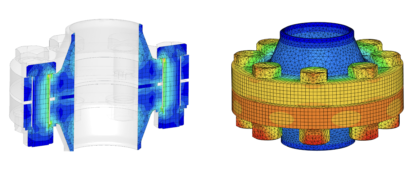
Static Analysis
The static analysis type allows time-independent calculation of displacements, stresses, and strains in one or multiple solid components. The results are a consequence of the applied constraints and loads, for example, bearings, gravity, forces, etc.
The results enable engineers to evaluate if the component of interest deforms in an undesired manner. Will help understand if a critical stress state occurs that will pose threat and risk failure. Feel free to check the following bolted flange example to get an idea of static structural analysis example.
Dynamic Analysis
The dynamic analysis type allows time-dependent calculation of displacements and stresses/strains in one or multiple solid components. Comparing it to a simple static analysis, it now differs due to the fact that inertia effects are also taken into consideration through variation in time.
The results allow engineers to analyze single timesteps as well as the dynamic performance as a function of time. Similar to static analysis, the model adequacy with respect to maximum allowable stresses and deformations can be assessed over time. Drop-test and impact assessments are characteristic examples of dynamic structural analysis.
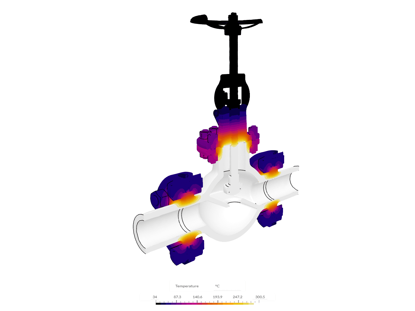
Thermomechanical Analysis
The thermomechanical analysis is beneficial when trying to compute the combined thermal and structural behavior of a component or assembly. It is actually helpful in calculating the stresses of a solid body caused by combined thermal and structural loads. The calculation of the thermal and structural results is sequential. The process typically starts with a thermal step which then serves as input to a consecutive structural step. It is essentially a combination of a thermal and structural analysis.
Studying the thermal shock of components, like a spark plug or a globe valve, comprise typical thermomechanical application examples.
Frequency and Harmonic Analysis
The frequency Analysis simulation type allows the computation of natural (under no external load excitation) frequencies (eigenfrequencies) of oscillation of a structure. It also permits the calculation of the corresponding oscillation mode shapes (eigenmodes). The resulting frequencies and deformation modes depend on the geometry and material distribution.
Frequency analysis results help evaluate the overall rigidity of the structure and understand what are the “dangerous” frequencies which might lead to resonance. Such results are a valuable input to seismic studies, wind loading studies or vibration studies. A quite common example is vibration studies of electronic equipment like in this Electric Vehicle (EV) battery module.
The frequency analysis is often the first step to a later Harmonic Analysis. The harmonic analysis enables the engineers to simulate the steady-state structural response of solids excited by periodical (sinusoidal) loads. It is quite similar to a dynamic analysis where inertia effects are taken into account, but it is different in the sense that now the results are no longer time-dependent but frequency-dependent. In other words, the harmonic analysis makes it possible to compute the response of a structure under vibrating forces or displacements over a defined frequency spectrum. Such studies can also take damping effects into account.
The EV battery module case mentioned above is a nice example of a combined frequency and harmonic analysis simulation for electronic equipment.
| Eigenmode | Eigenfrequency |
| 1.0 | 233.433 |
| 2.0 | 236.206 |
| 3.0 | 251.691 |
| 4.0 | 362.203 |
| 5.0 | 364.132 |
Structural Analysis With SimScale
You can start exploring all the different structural analysis types with SimScale. You can leverage cloud computing tools and simulate hundreds of designs in parallel on the cloud without the need for any sophisticated hardware — right from your web browser.
If you liked this article and you are new to FEA, do not miss our FEA Guide, which will give you enough material to get you started. Try our structural and thermomechanical tutorials now and explore the different plans that can bring you onboard.
Frequently Asked Questions
Structural analysis is the process of predicting how a structure will respond to loads, vibrations, and other physical effects. Engineers use it to determine internal stresses, deformations, reaction forces, and failure modes before a part or building is built. Modern structural analysis is almost always performed numerically using the finite element method (FEM), implemented in finite element analysis (FEA) software.
The most common types are linear static (steady loads, small deformations), modal (natural frequencies and mode shapes), dynamic (time-dependent loads, including harmonic, transient, and shock), buckling (stability under compressive loads), nonlinear (large deformations, plasticity, contact, hyperelastic materials), thermal-stress (loads from temperature changes), and fatigue (life prediction under cyclic loading). Most real-world simulations combine two or more of these.
Structural analysis is the engineering discipline — the questions you’re asking (will this beam yield? at what frequency does this bracket resonate?). FEA is the numerical method most commonly used to answer those questions — it discretizes a structure into finite elements and solves the governing equations of solid mechanics. You perform structural analysis using FEA, in the same way you perform fluid analysis using CFD.
Static structural analysis assumes loads are applied slowly enough that inertial effects (mass × acceleration) can be ignored. The structure reaches equilibrium at every load step. This is the most common type of FEA simulation and is appropriate for most strength, stiffness, and stress-checking problems where loads do not change rapidly. If loads vary in time, vibration matters, or impact is involved, dynamic analysis is required instead.
Nonlinear structural analysis is required whenever the response of a structure is not proportional to the applied load. The three most common sources of nonlinearity are material (plasticity, hyperelasticity in rubbers and polymers), geometric (large deformations, buckling, snap-through), and contact (parts coming into and out of contact, friction). Nonlinear simulations require iterative solvers and are computationally heavier than linear analyses, but are essential whenever your structure yields, deforms significantly, or relies on contact behavior.
FEA divides a structure into a mesh of small finite elements, each of which has known stiffness behavior. The software assembles these into a global system of equations representing the entire structure, then solves for the displacements that balance the applied loads. From the displacements, it computes strain, stress, and reaction forces at every point. This makes it possible to analyze complex geometries and loading conditions that would be impossible to solve by hand.
Common commercial FEA tools include Ansys Mechanical, Abaqus, Nastran, and SolidWorks Simulation. Cloud-native platforms like SimScale run structural analysis directly in a browser, which removes the need for high-performance workstations and on-premise licenses. Selecting the right tool depends on the type of analysis (linear vs nonlinear, static vs dynamic), required solver capabilities, budget, and team workflow.
A typical workflow has six steps: (1) define geometry and import or simplify the CAD model; (2) assign materials with the right constitutive model; (3) apply boundary conditions, contacts, and loads; (4) generate a mesh appropriate to the analysis type and required accuracy; (5) run the solver and check for convergence; and (6) post-process results — stresses, displacements, factor of safety, and any required design checks. Mesh refinement and convergence studies are essential to validate results.
References
- “Wikimedia commons: Stress Strain Ductile Material.”
- T.H.G. Megson, Aircraft Structures for Engineering Students
Last updated: May 3rd, 2026
Did this article solve your issue?
How can we do better?
We appreciate and value your feedback.
What's Next
What is von Mises Stress?

