
Rotating Zones
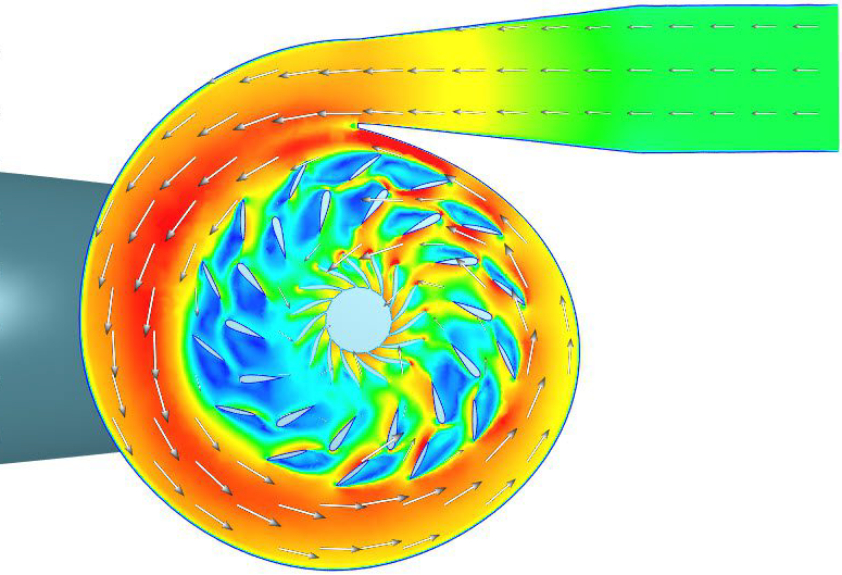
Rotating zones can be used to model rotating systems such as turbines, fans, ventilators, and other similar systems. This documentation page shows how simulation with rotating zones can be set up.
Note
Rotating zones are only available for the following analysis types:
– Incompressible
– Compressible
– Convective heat transfer
– Conjugate heat transfer
– Conjugate Heat Transfer (IBM)
– Multiphase, only if Local time stepping is disabled in the global settings
– Multi-purpose
CAD Requirements
Simulations with rotating zones require special attention during CAD preparation. The requirements are described at length in the following knowledge base article:
Simulation Setup
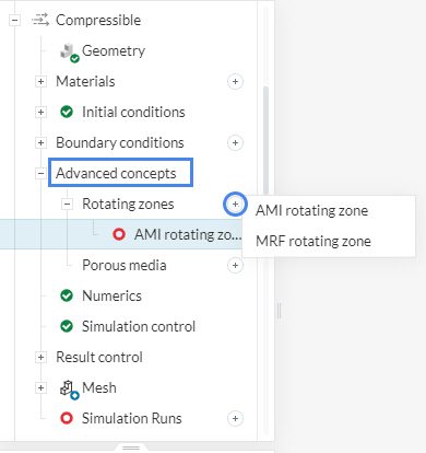
In the simulation tree, navigate to Advanced concepts and click on the ‘+’ button next to Rotating zones. Two types of rotating zones are supported: Multiple Reference Frame (MRF) and Arbitrary Mesh Interface (AMI).
(MRF) Rotating Zones
The MRF rotating zone is a steady-state approximation of the transient rotating motion at an “instance” of time. Therefore, the mesh/body is not physically rotated. One must make sure that the problem does not include large-scale transient phenomena.
This approach uses a rotating frame of reference that modifies the governing equations in the rotating zone. Additional source terms that incorporate forces in the rotating reference frame are taken into account. These simulate a rotation effect in the flow.
Performing MRF simulations is computationally much less demanding than transient modeling. Hence, if the problem is set up correctly, MRF provides good approximations with less computational effort and considerably less computation time.
Setup of an MRF Rotating Zone
Figure 3 shows the setup interface for an MRF rotating zone:
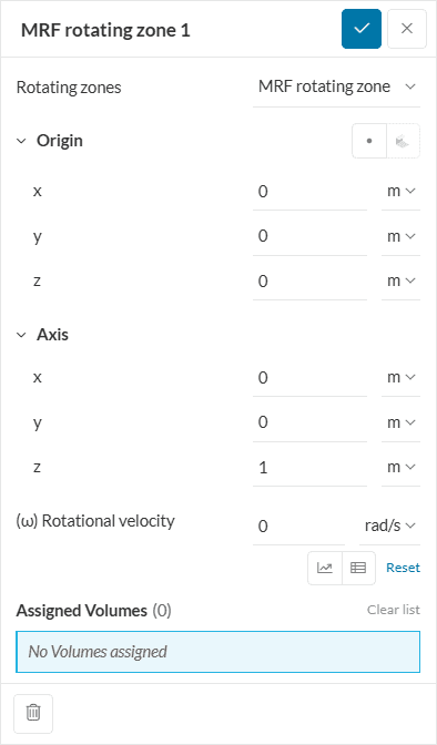
- Under Origin, the user should define the center point coordinates for the rotating zone;
- The Axis entry defines around which axis the rotating zone will be spinning. The direction of rotation is given by the right-hand rule;
- The final input is the Rotational velocity, given in \(rad/s\) or \(º/s\). Note that the rotational velocity can be parametrized in SimScale, as this article shows;
- Lastly, assign the rotating zone to its corresponding volume.
Did you know?
In the right-hand rule, the rotation axis is represented by the right-hand thumb. The motion of the other four fingers indicates the direction of the rotation.
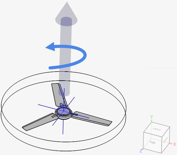
In the figure above, the rotation axis was defined in the positive y-direction. The blue arrow indicates the resulting direction of the fan rotation.
(AMI) Rotating Zones
AMI rotating zone simulations are fully transient and, therefore, are computationally much more expensive than MRF. They take all transient effects into account and are usually sensitive to the time step length.
In the AMI approach, a mesh interface is created between the moving and stationary parts of the mesh. At each time step, the rotating zone is physically rotated, and quantities are interpolated at this interface to allow realistic movement of the rotating parts.
Note
In cases where large-scale transient phenomena are not observed within the rotating zone, it’s still possible to use the MRF approach, even for transient simulations.
Setup of an AMI Rotating Zone
Figure 5 shows the setup window for an AMI rotating zone:
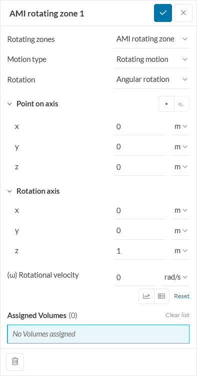
- Motion type can be specified as Oscillating or full Rotating motion. An oscillating motion also requires the definition of its Amplitude;
- The Rotation can be defined as an Angular rotation or vector rotation;
- A Point on the rotation axis should be provided for the rotating zone;
- The Rotation axis needs to be defined. The right-hand rule also applies in this case;
- Lastly, the Rotational velocity should be set, and a rotating volume should be assigned. Again, the rotational velocity supports a parametric definition.
Radiation and Rotating Zones
Whether radiation can be used together with a rotating zone depends on the analysis type. The table below summarizes the supported combinations:
| Analysis type | Rotating zone type | Radiation | Supported |
|---|---|---|---|
| Conjugate Heat Transfer | MRF (steady-state) | Enabled | Yes |
| Convective Heat Transfer | MRF or AMI | Enabled | No |
Conjugate Heat Transfer with MRF and Radiation
In a steady-state Conjugate Heat Transfer simulation, radiation can be enabled alongside an MRF rotating zone. Both features can be configured independently in the simulation tree and the simulation will run with both active, as shown in Figure 6.
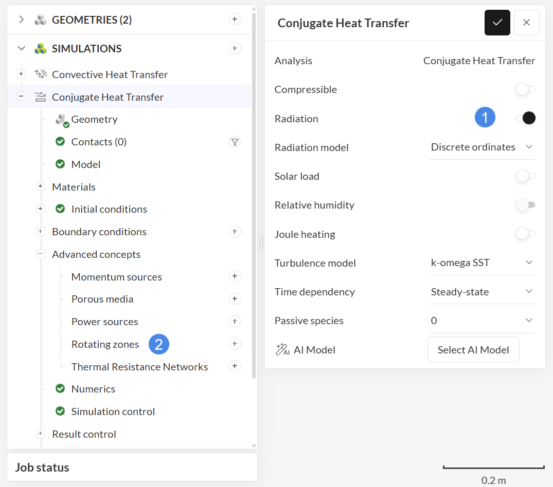
The radiation transport equations are solved in the stationary (absolute) reference frame, not in the rotating frame used by the MRF zone. This means that the radiation field — including view factors, absorbed flux, and emitted flux — is computed as if all surfaces are at rest in the lab frame. The resulting radiative heat flux is then applied as a thermal boundary condition at each surface, which is subsequently coupled to the temperature solution in both the fluid and solid regions, including any region covered by an MRF rotating zone.
Note
The radiation solution does not account for the physical rotation of surfaces inside an MRF zone. Surface orientations and positions used for radiation computations correspond to the geometry as defined in the CAD model, not to any rotated state. For applications where the angular position of radiating surfaces significantly affects the radiation exchange — for example, a rotating heat source with strong directional emission — consider whether a transient approach with AMI is more appropriate.
Convective Heat Transfer with Radiation
In a Convective Heat Transfer simulation, rotating zones are not available when radiation is enabled. If radiation is turned on in the simulation settings, the Rotating Zones option will not appear in the Advanced Concepts section of the simulation tree. This combination is not supported, as shown in Figures 7 and 8.
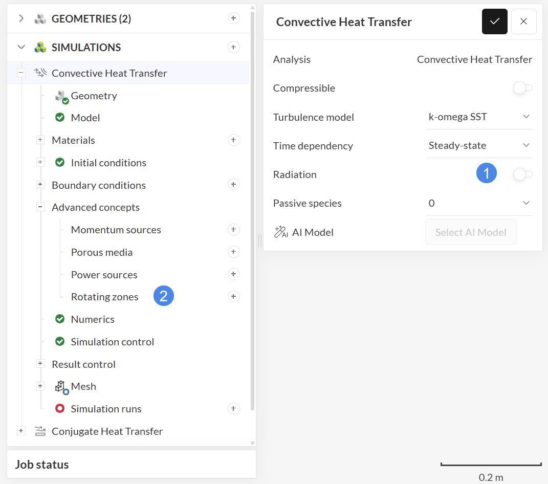
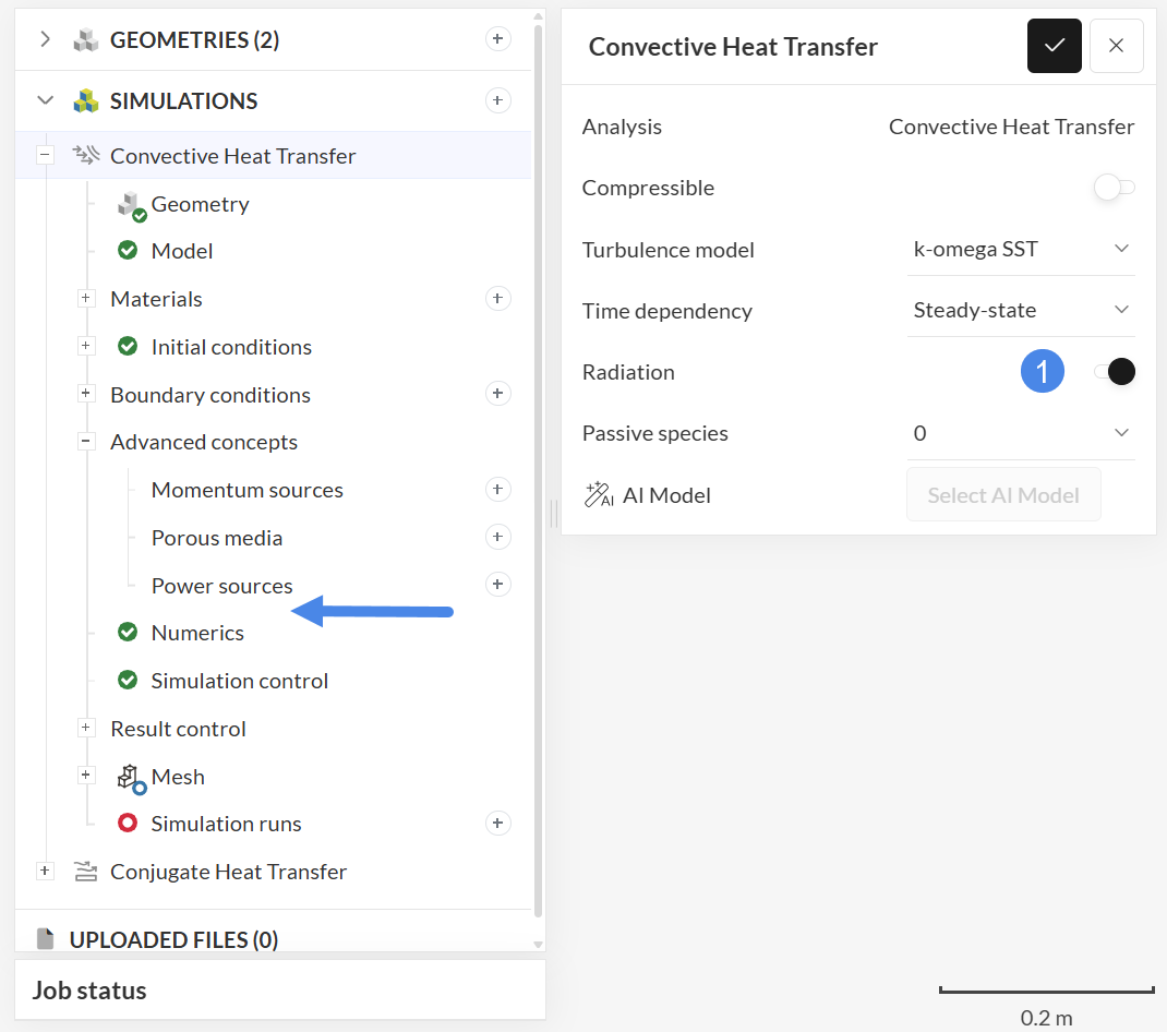
If your application requires both a rotating component and radiation, use the Conjugate Heat Transfer analysis type instead. CHT supports solid bodies alongside the fluid domain and is the recommended analysis type for thermal simulations involving rotating machinery with heat radiation.
Important
Enabling radiation in a Convective Heat Transfer simulation removes the Rotating Zones option from the simulation tree. To use both rotating zones and radiation in the same simulation, switch to the Conjugate Heat Transfer analysis type.
Mesh Preparation
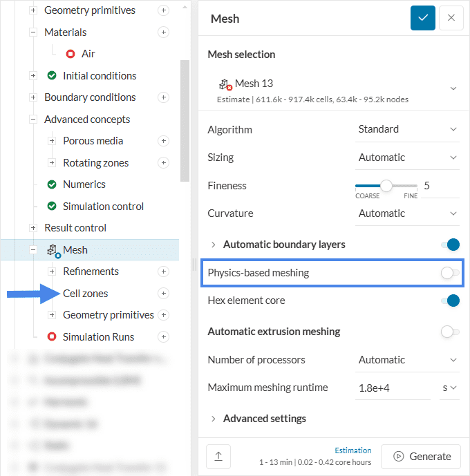
In the mesh set up, the rotating zone volume needs to be defined as a Cell zone. The workflows to define cell zones are different, depending on the meshing algorithm. Find below the steps for each of the cases.
Standard Mesher
When using the standard mesher with physics-based meshing enabled, the algorithm automatically creates cell zones for the regions selected for any of the entries in Advanced concepts.
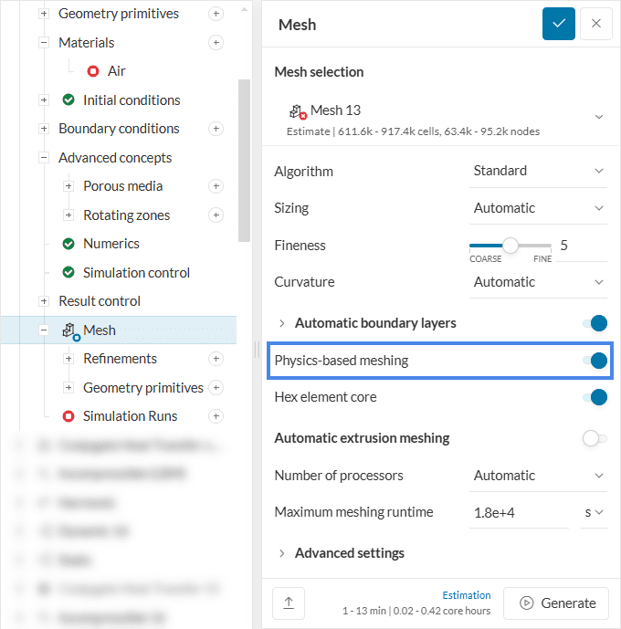
When Physics-based meshing is disabled, the user needs to manually define the cell zones, as in Figure 7:
Hex-Dominant Meshes
For hex-dominant meshes, the creation of a cell zone is done by adding surface refinements. When adding additional refinements in a hex mesher choose the surface refinement option.
In the settings panel, make sure Cell zone is set to ‘With cell zone’ and give a name accordingly to distinguish between multiple cell zones.
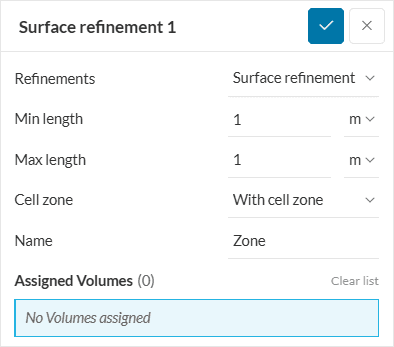
For a cell zone to be created, a closed volume (or all faces of the closed volume) needs to be assigned to the surface refinement. If successful, all cells enclosed by the assigned volume will be grouped together.
Learn more about surface refinements in our hex-dominant mesh document:
Tutorials
For a practical guide on how to set up and use rotating zones, take a look at the following tutorials:
- Advanced Tutorial: Fluid Flow Simulation Through a Centrifugal Pump
- Advanced Tutorial: Flow Simulation Through a Water Turbine
Last updated: September 24th, 2026
Did this article solve your issue?
How can we do better?
We appreciate and value your feedback.






