The Incompressible LBM solver offers three types of output fields for a simulation: Transient output, Statistical averaging, and Snapshot. From these three, the transient output is the only one that writes the fields as a function of time. As such, it is important to know the time step size that will be used in the transient output fields.
This value is controlled by two parameters, as found in the Transient output panel: Write control and Fraction from end:
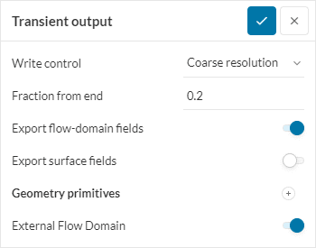
The Fraction from end determines the total period of time written, as a proportion of the End time under Simulation control. In the example given in Figure 1, the last 20% of the simulated time will be written.
On the other hand, the Write control determines the time step size. If set to Manual, the step size can be input directly. If an automatic resolution is used, then the step size is computed as a proportion of the simulation time step.
Computing the Automatic Time Step Size
The automatic time step size in the transient output is computed using the following equation:
$$ \Delta t_{out} = \Delta t_{sim, max} \cdot c_{res} \tag{1} $$
Where:
- \( \Delta t_{sim, max} \) is the maximum time step size used in the simulation, computed as shown below.
- \( \Delta t_{out} \) is the time step size of the transient output
- \( c_{res} \) is the resolution coefficient, given in Table 1:
| Write Control | Resolution Coefficient |
|---|---|
| Coarse resolution | 8 |
| Moderate resolution | 4 |
| High resolution | 2 |
The simulation time step size is computed as a function of the mesh size:
$$ \Delta t_{sim} = \frac{ h \times\ velocity\ scaling }{U_{ref} } \tag{2} $$
Where:
- \( h \) is the minimum or maximum cell size
- \( U_{ref} \) is the reference flow speed, as applied at the inlet face
- \(velocity scaling\) is a simulation control parameter set to improve simulation stability
It is important to notice that the solver determines a minimum and a maximum time step, based on the corresponding cell sizes. For the transient output, the maximum time step is used as a base for the computation of the output step size.
Determining the Cell Size
The cell size is a function of the reference length and the fineness specified under mesh settings.
For Automatic Meshing:
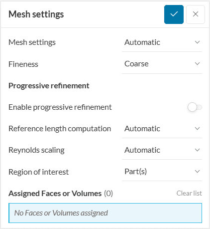
$$ h_{max} = \frac{ L_{ref} }{ n } \tag{3} $$
$$ h_{min} = \frac{ h_{max} }{ 2^{m} } \tag{4} $$
Where:
- \(h_{max}\) is the maximum cell size
- \(h_{min}\) is the minimum cell size
- \( L_{ref} \) is the reference length value specified manually as a Value or automatically computed
- \( n \) is the number of cells per length
- \( m \) is the number of refinement levels
\(n\) and \(m\) are defined from the Fineness parameter according to Table 2:
| Fineness | Number of Cells per Length, \(n\) | Number of Refinement Levels, \(m\) |
|---|---|---|
| Very coarse | 16 | 4 |
| Coarse | 16 | 5 |
| Moderate | 24 | 5 |
| Fine | 16 | 6 |
| Very fine | 24 | 6 |
For Manual Meshing:
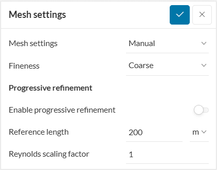
$$ h_{max} = \frac{ L_{ref} }{ n } \tag{3} $$
$$ h_{min} = \frac{ h_{max} }{ 2^{m^*} } \tag{5} $$
$$ m^* = ceil \left( log\ 2 \left[ \frac{1}{lbm_{length}} \right] \right) \tag{6}$$
Where:
\(m^*\) is the final maximum refinement level
\(lbm_{length}\) is the Fineness specified but converted to LBM units
Important
The ceil function always rounds up fractions to the nearest integer value greater than the integer part, even for negative numbers. For example, ceil(3.8) returns 4, ceil(3.2) also returns 4 and, ceil(-3.8) returns -3. The ceil function rounds up fractions to the nearest integer.
Example Computation for Automatic Meshing
To demonstrate the computation, let’s assume a case with the following parameters:
- Reference length \( L_{ref} = 200\ m \)
- Inlet velocity \( U_{ref} = 10\ m/s \)
- Mesh fineness is Coarse
- Write control under Transient output has Coarse resolution
Then we proceed to the computation:
From table 2, the number of cells per length \( n = 16 \) and the number of refinement levels \( m = 5 \)
The maximum cell size is computed from equation 3:
$$ h_{max} = \frac{ 200\ m }{ 16 } = 12.5\ m $$
And the minimum cell size from equation 4:
$$ h_{min} = \frac{ 12.5\ m }{ 2^5 } = 0.391\ m $$
The time step size range for the simulation will be:
$$ \Delta t_{sim, min} = \frac{ 0.391\ m }{ 10 (10\ m/s) } = 3.91\ ms $$
$$ \Delta t_{sim, max} = \frac{ 12.5\ m }{ 10 (10\ m/s) } = 0.125\ s $$
From table 1, the resolution coefficient is \( c_{res} = 8 \)
Finally the output time step is computed from the maximum time step size:
$$ \Delta t_{out} = (0.125\ s)(8) = 1\ s $$
Note
If none of the above suggestions solved your problem, then please post the issue on our forum or contact us.


