In a typical thermal comfort study, the HVAC heating equipment like climate ceilings, radiant panels, or high power lights plays an important role in the heating of the indoor environment. Let us briefly describe these to understand the heating mechanisms.
Climate Ceiling
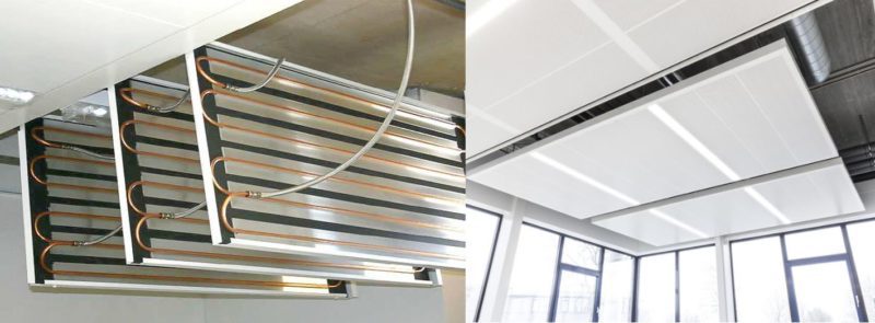
Through the structure, hot (or cold) water can be transported depending on whether heating or cooling is needed in the concerned space. Energy exchange primarily takes place based on radiation, which is perceived as very pleasant.
Radiant Panels
Radiant panels, similar to the climate ceiling, heat a building through radiant heat, rather than conventional methods.
The heat energy is emitted from a warm element, such as a floor, wall, or overhead panel, and warms people and other objects in rooms rather than directly heating the air. The metal surfaces release energy as mostly radiation.
Benefits for the working environment
- Always a pleasant and uniform temperature due to radiation and high cooling and heating capacities;
- Low air speeds (minimum surface convection) and thus no draught or dust displacement;
- High acoustic comfort; silent system and pleasant acoustics due to noise damping capacity of ceiling panels.
- The ability to configure temperature separately in each room.
Modeling Climate Ceiling/Radiant Panels in SimScale
The boundary condition set up for modeling the concepts that were previously described is included as a no-slip wall set:

The (U) Velocity defines the type of the surface, and specifically, the No-slip condition stands for a solid wall where velocity is zero at the surface. The Turbulence wall setting clarifies the way the boundary layer will be generated on the wall. Wall-function is one of the available methods for the generation. You can learn more about the wall boundary condition here.
As seen above, the user specifies the heating amount as Heat Flux in \(W/m^2\) and the panel/surface is allowed to emit radiation with high emissivity between 0.8-0.95 to minimize convection based on the design.


