For simulations involving Conjugate heat transfer (CHT) analysis, the requirements for the simulation domain are slightly different from the normal procedure where we create a flow volume covering the negative of our overflowed geometry which represents the physical walls. This article describes how to proceed with CHT simulations ensuring the flow domain is accurately created.
Approach
Import the following geometries into your Workbench by clicking the button:
Clicking the link leads to the following Workbench view:
The project contains two geometries. The first one, named Electronics Box Missing Flow Region, still needs a final CAD preparation step before it can be used in a simulation.
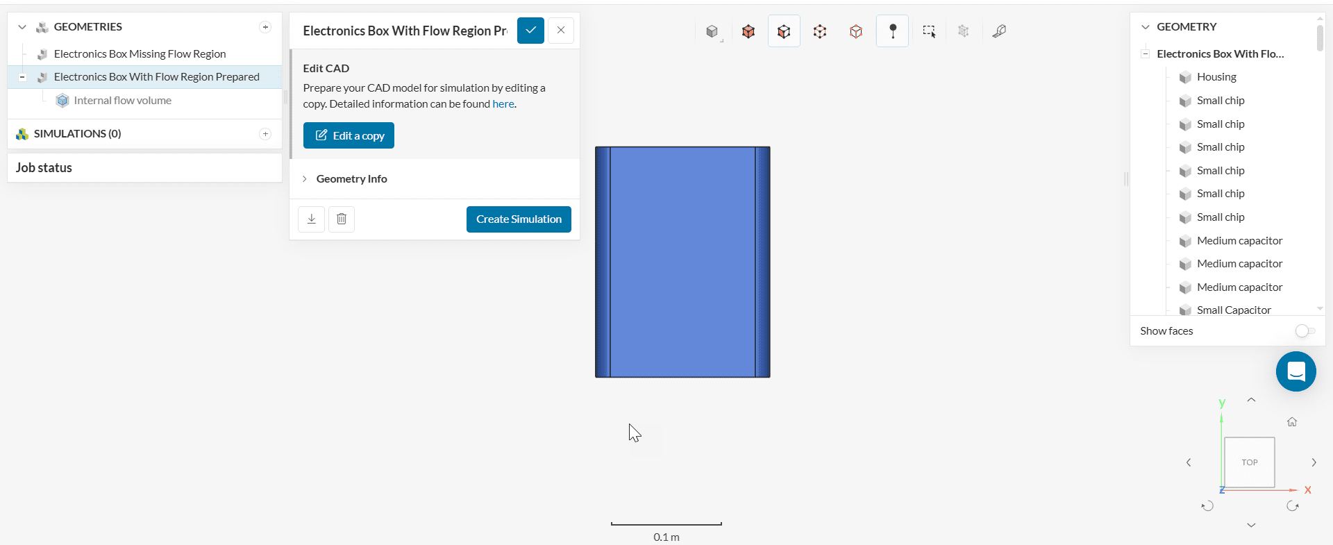
The second geometry, Electronics Box Flow Region Prepared, is the final complete geometry that we aim for with this approach.
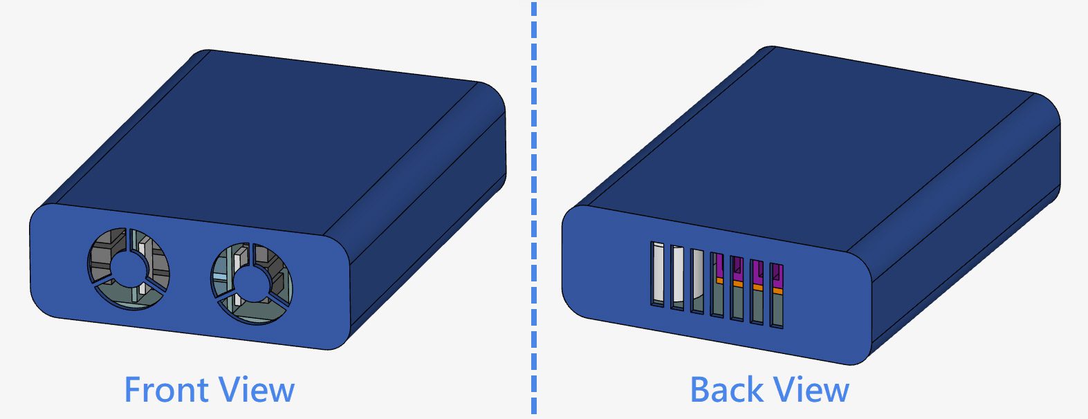
CHT simulation involves heat transfer through both solids and fluids. Hence, we need to keep the original solid parts while extracting the fluid volume as they participate in the heat transfer too. Usually, the CAD model only involves solid parts, as you can see in the first geometry:
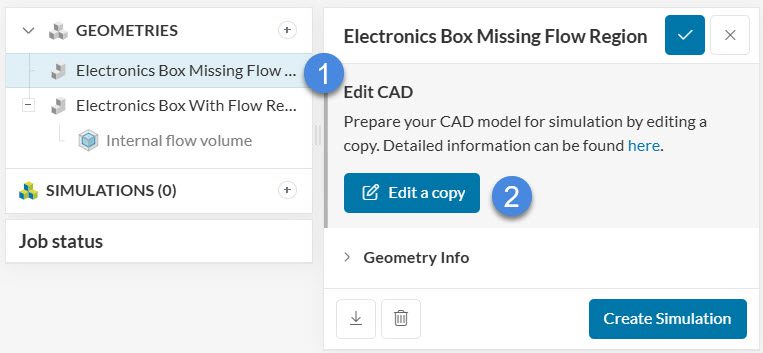
To begin creating a fluid flow volume select the geometry ‘Electronics Box Missing Flow Region’ and click ‘Edit a copy’:
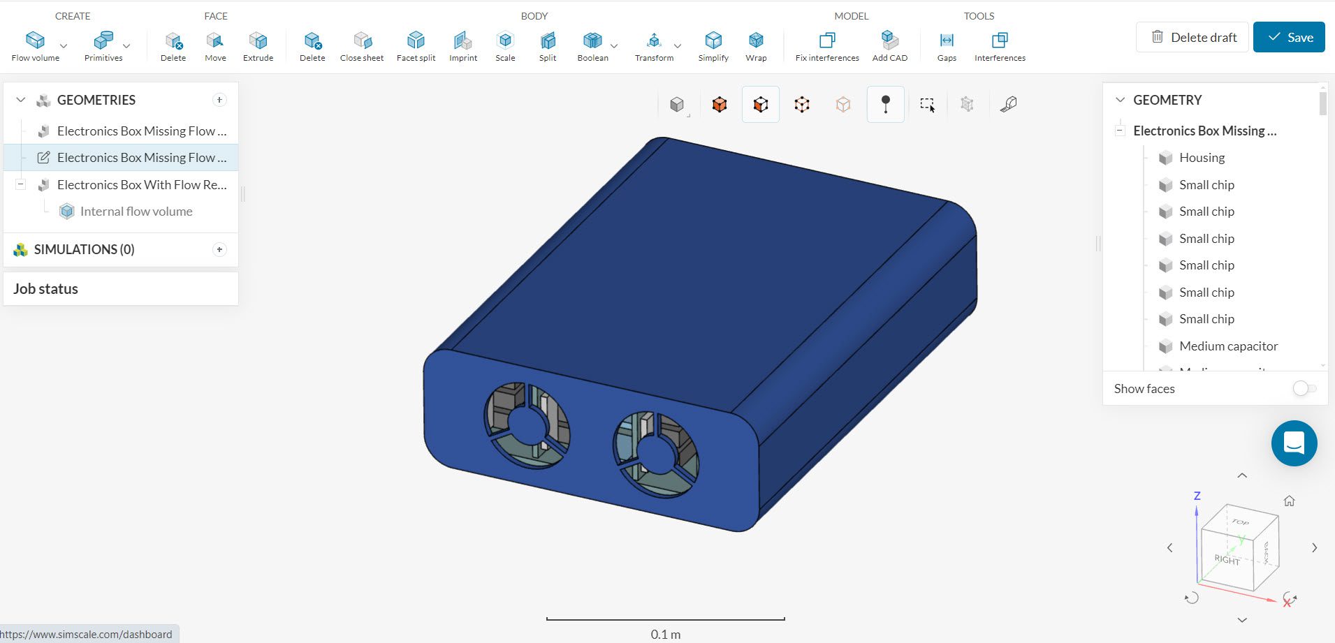
After selecting the first geometry and clicking on ‘Edit a copy’, a draft of the CAD model will be created for editing. The interface looks as follows:
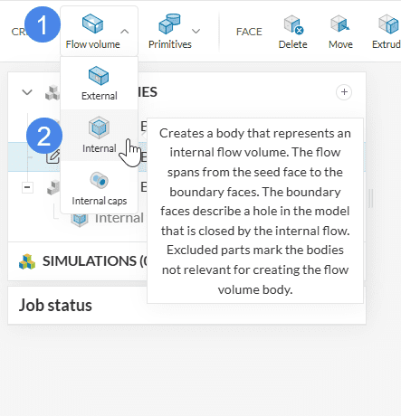
Next, create an internal flow volume operation by hovering over the Flow Volume icon and selecting ‘Internal’.
To create the internal fluid volume, select a face of the housing that will be adjacent to the boundary face. This will define a starting point (source) for the internal fluid volume creation and is referred to as a seed face.
Since the housing of the electronic box has two open faces, we have to define two boundaries, which will limit the creation of the internal fluid volume. For the electronic box, select the front and the back of the housing as the boundaries.
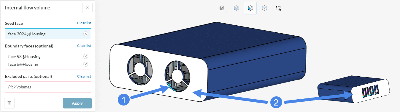
Once the settings panel looks as above, hit ‘Apply’.
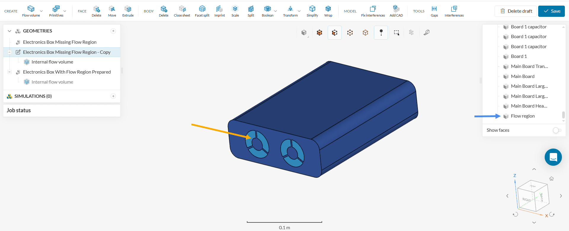
If the flow volume operation is successfully performed, you will see a newly created solid body Flow region inside the Scene tree. The default color of the flow region is blue, as in the following picture:
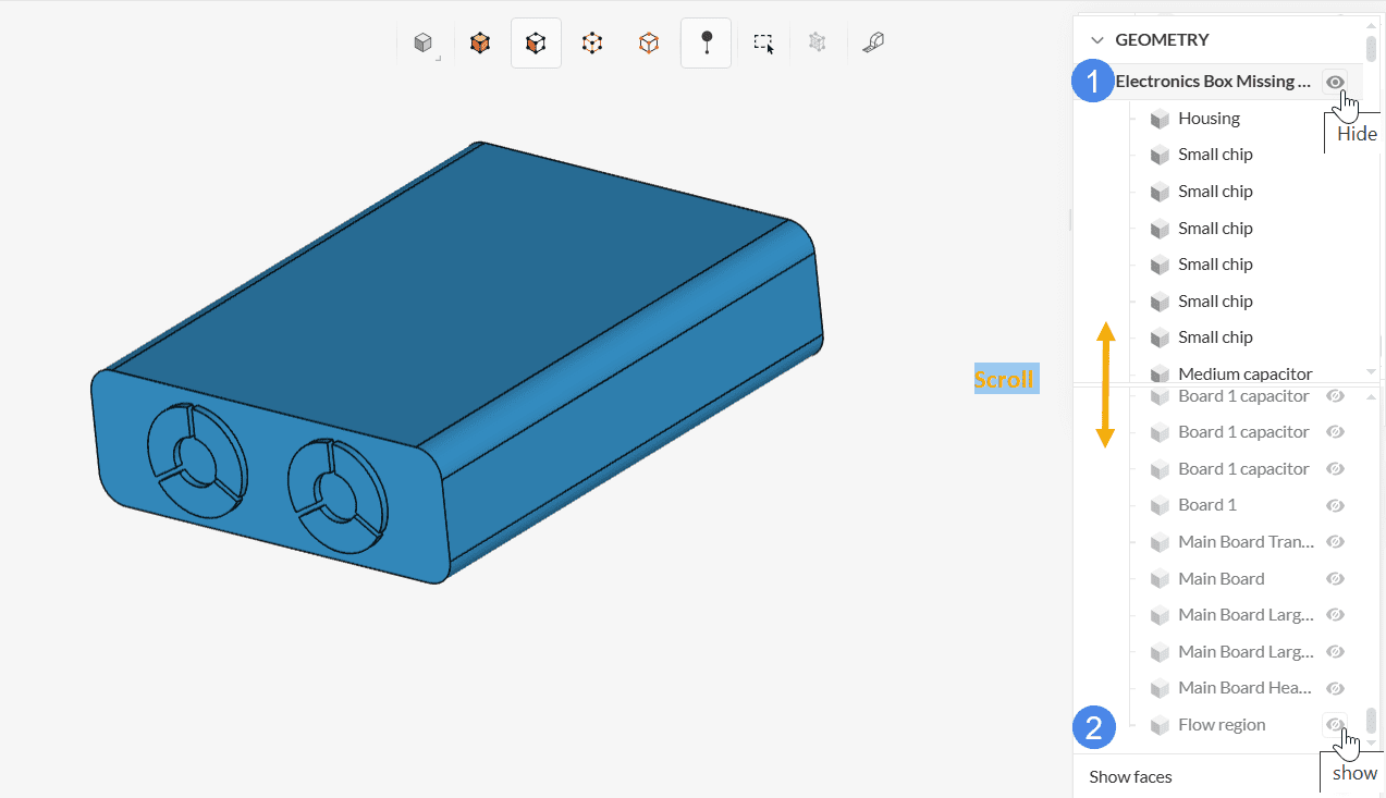
To observe just the flow volume created, hide all the other parts. This can be done by hiding the whole CAD first and then showing only the Flow region.
Now you can exit CAD editing tool by clicking on the ‘Save’ button (top right, see Figure 7). This will save the latest version of your draft as a new model under the Geometries list named with “Copy of …” prefix. The name can be edited as preferred.
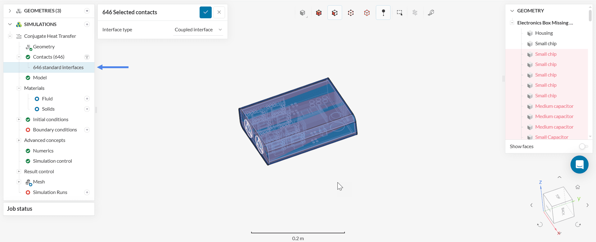
Interface Detection
When we create the CHT simulation, the tool detects the interfaces between the solid and fluid regions automatically and hence, no further CAD operation is necessary.
Note
If none of the above suggestions solved your problem, then please post the issue on our forum or contact us.


