The objective of this article is to give some insights on how to prepare and extend a terrain using Rhino, in order to obtain a model ready for simulation in the Pedestrian Wind Comfort (PWC) analysis type in the SimScale platform.
Background
When doing a Pedestrian Wind Comfort analysis, it is known that the topology cannot be ignored, and should be included in the analysis. SimScale requires that the topology needs to extend beyond the limits of the simulated region. This is for two main reasons, firstly it prevents flow from moving under the surface, and secondly, it ensures that there is a defined floor to the simulation, even if it is uneven. You can read more about why it is necessary to have the topology extended here. However, it is common that we just do not have any more of the topology to extend this far. For this reason, we advise that terrain is extended artificially in software such as Rhino, and in the following article, we describe the workflow and present an example.
Overview
When preparing geometry for the PWC analysis, the user should start by defining the main Region of Interest in the project, which will be referred to by ROI. The importance of this is to ensure that the ROI is kept at the center of the geometry, and we can make sensible limits based upon the center of the region (usually where a new complex or building is proposed to be developed).
Note
It might be useful to first turn all the unnecessary layers off, normally leaving only the buildings and the topography visible.
Solution
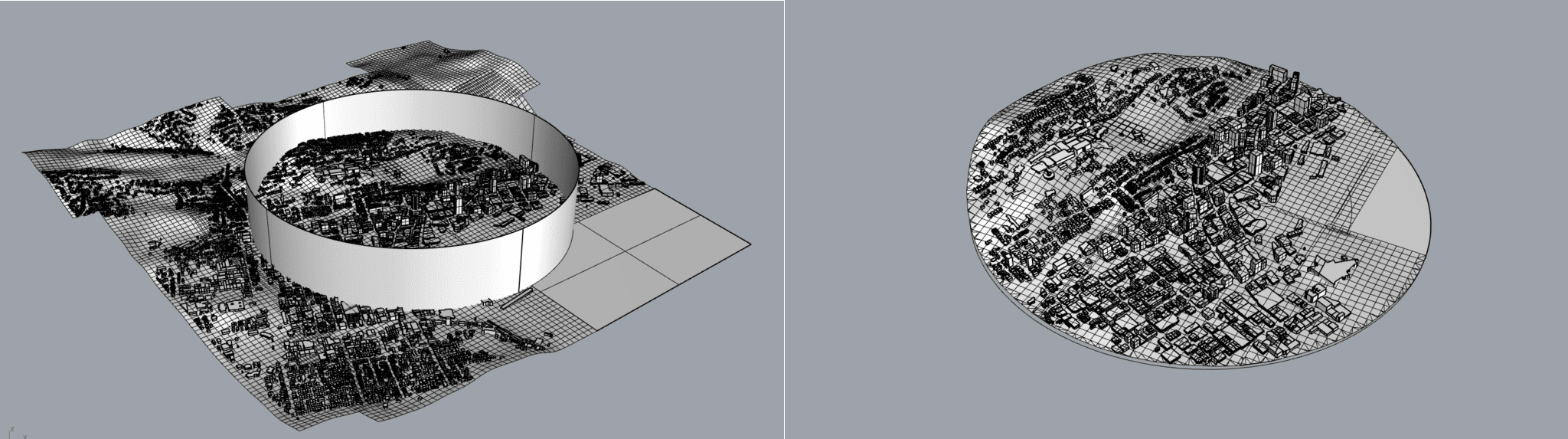
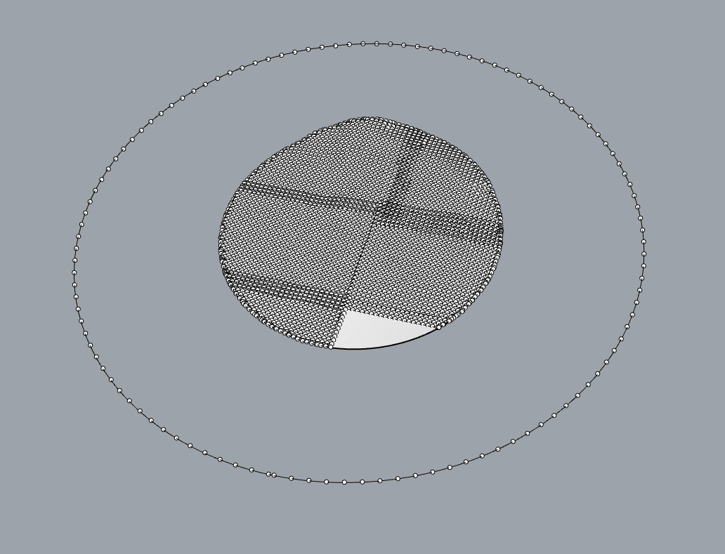
Depending on the topography and the surroundings of the ROI, a circle should be defined with a sensible radius, centered on the epicenter of our ROI. This circle will define the region of inclusion, meaning the region containing the ROI and the surroundings that may be interesting to study with a PWC analysis. If this area is missing some material that will generate future problems in the mesh, there is a need to identify and eliminate those gaps or anomalies. In order to simplify the model and optimize its efficiency, the components not inside the area of inclusion should be removed. As a rule of thumb, the ROI radius plus 500 \(m\) could be used as the radius for this inclusion circle, however, this can be altered with the best judgment from the user.
At this point, you will have buildings, context, and terrain centered on the ROI. However, we now need to extend that beyond the simulation limits. To start extending the terrain, a new circumference should be created again using the ROI center as the reference point. This new circle added, determines the limits of the final model and, for that reason, its diameter should be wider than the one previously defined.
As a rule of thumb, you can extend to a radius of 2500 \(m\), this is, however, much larger than required in most cases, and usually, a more sensible radius is the radius of the ROI, plus 20 times the tallest building height. Hence, if a building was 100 \(m\) tall from the lowest point, and the ROI radius was 300 \(m\) then your extension radius could be 2300 \(m\) or 2.3 \(km\).
Worked Example with MeshPatch
This example is from a Terrain CAD File from the area of Wellington, New Zealand, extracted from an online source named CADMAPPER.
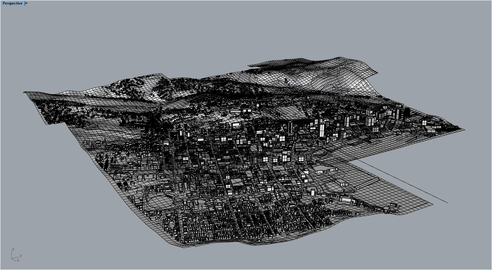
There is a lot of unnecessary information in the model, so all the unnecessary layers should be turned off. Extra information like lost lines or points is removed using the delete function on the Command-Box.
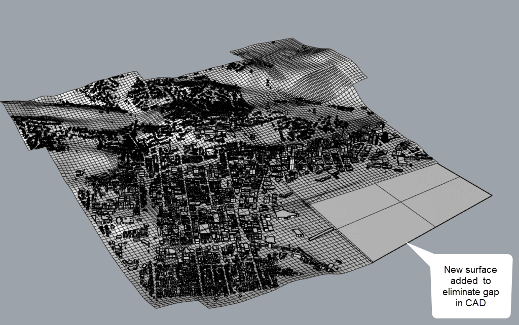
Some small manual preparation is usually needed, for example, when dealing with gaps, between buildings and the terrain, it is recommended to extrude the building floors for a small distance to ensure that flow cannot move under the buildings and negatively affect the comfort. However, in particular cases with complicated geometries, there is a need for different approaches. In the example, there is also a surface missing on the model that should be added at the coast. Since the sea is expected to be flat and on one plane, a single surface was used.
The objective, as described before, is to create a terrain extension, with no holes or gaps, that extend beyond the limits of the simulation, and keeping only the recommended amount of detail. It’s important to recognize that we can’t include everything in a simulation, or at least you could but it’s not necessary. With that in mind, after creating a circle including the surroundings of the ROI, all the buildings outside of that should be eliminated.
The Trim, MeshTrim, and Change layer function is useful in this process. To use the Trim functions, a cylinder that intersects the model’s topology surface needs to be created using the function ExtrudeCrv. For this function, the reference selected is the circle and the extrusion distance can vary. There is only a need to make sure that the cylinder generated surrounds the area desired to be preserved.
In order to generate the limits of the final model, a circle can be defined and, to simplify the next steps, the circles previously made should be hidden since they have already served their purpose.
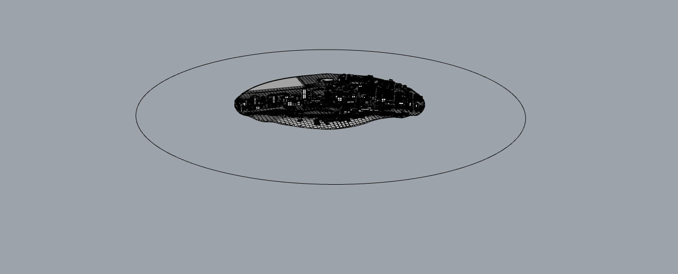
Using the function Divide curve by the number of segments, the points from the new circle line should be extracted. To collect the points that define the topography, the model should be selected and the function ExtractPt should be executed. If extra points appear between the limit circle and the model, they should be removed by simply deleting them.
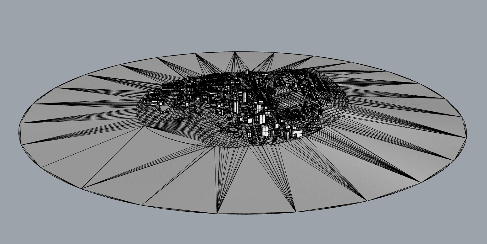
To finalize and generate the desired model, the function MeshPatch needs to be executed with all the points selected. In order to obtain the most simple and efficient model, all the points should be removed by selecting all the points with the function SelPt and erasing them with the Delete function. The relevant layers should be visible to obtain and visualize the final model.
Now the model can be uploaded to the SimScale platform as an STL. You can find how to upload and save a model as an STL from Rhino into SimScale in this link. Under, you will find a video that demonstrates step-by-step instructions presented during this article.
It is important to remember that there are multiple possibilities to achieve a similar model in Rhino however this particular method seems to be very efficient and robust.
Worked Example with Loft
In this second example, we will take a different approach, using the commands DupBorder, Offset, and Loft. First, we will start from a CAD model that has a short terrain:
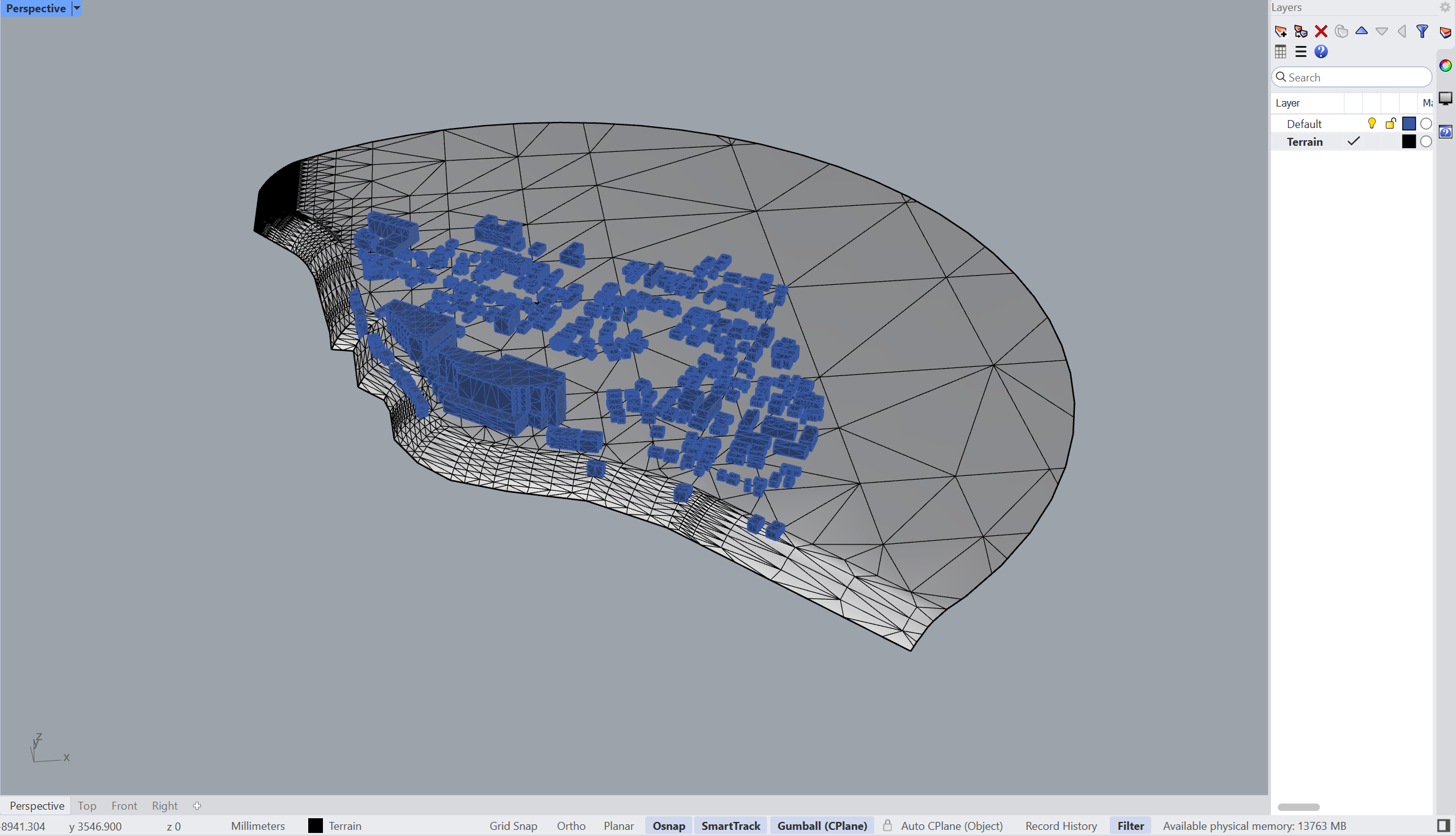
This terrain in particular is not very even, so extending it with the MeshPatch workflow outlined in the previous section may not be optimal.
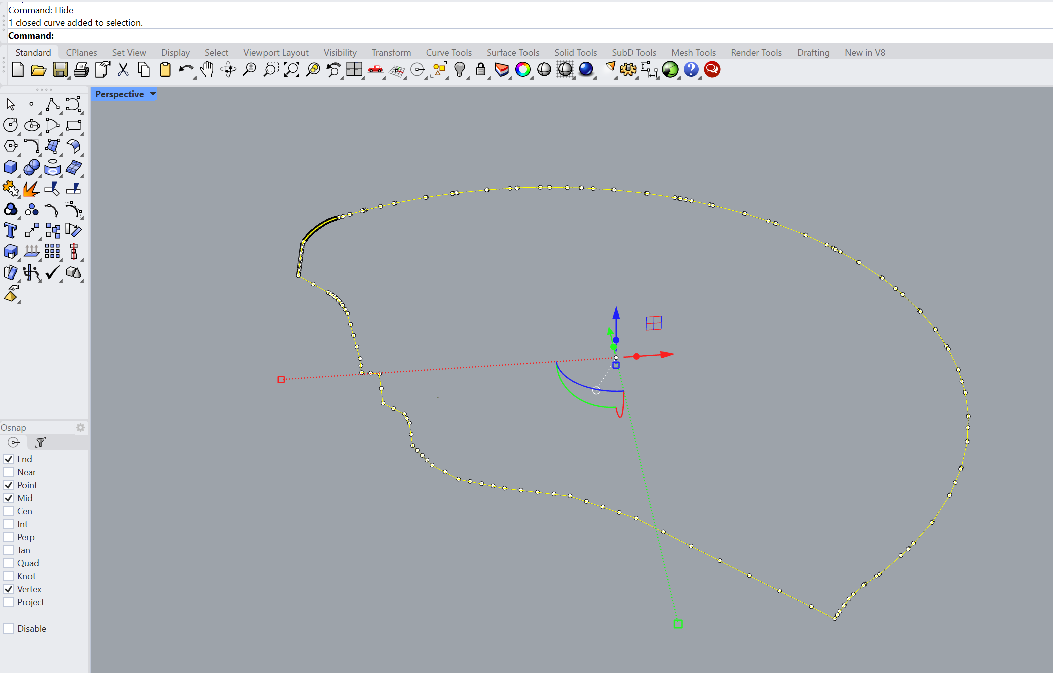
Instead, we can use the current terrain outline and further offset it, and then fill in the gap with a loft operation. For this, the first step is to select the terrain and use the DupBorder command, which duplicates the borders of the geometry:
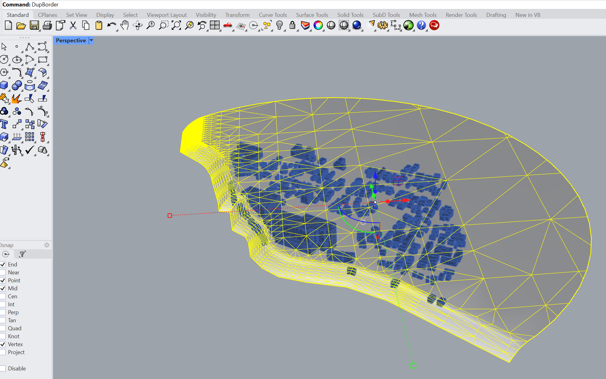
After running DupBorder and hiding the terrain and buildings, you will have a curve that captures the borders of the terrain:
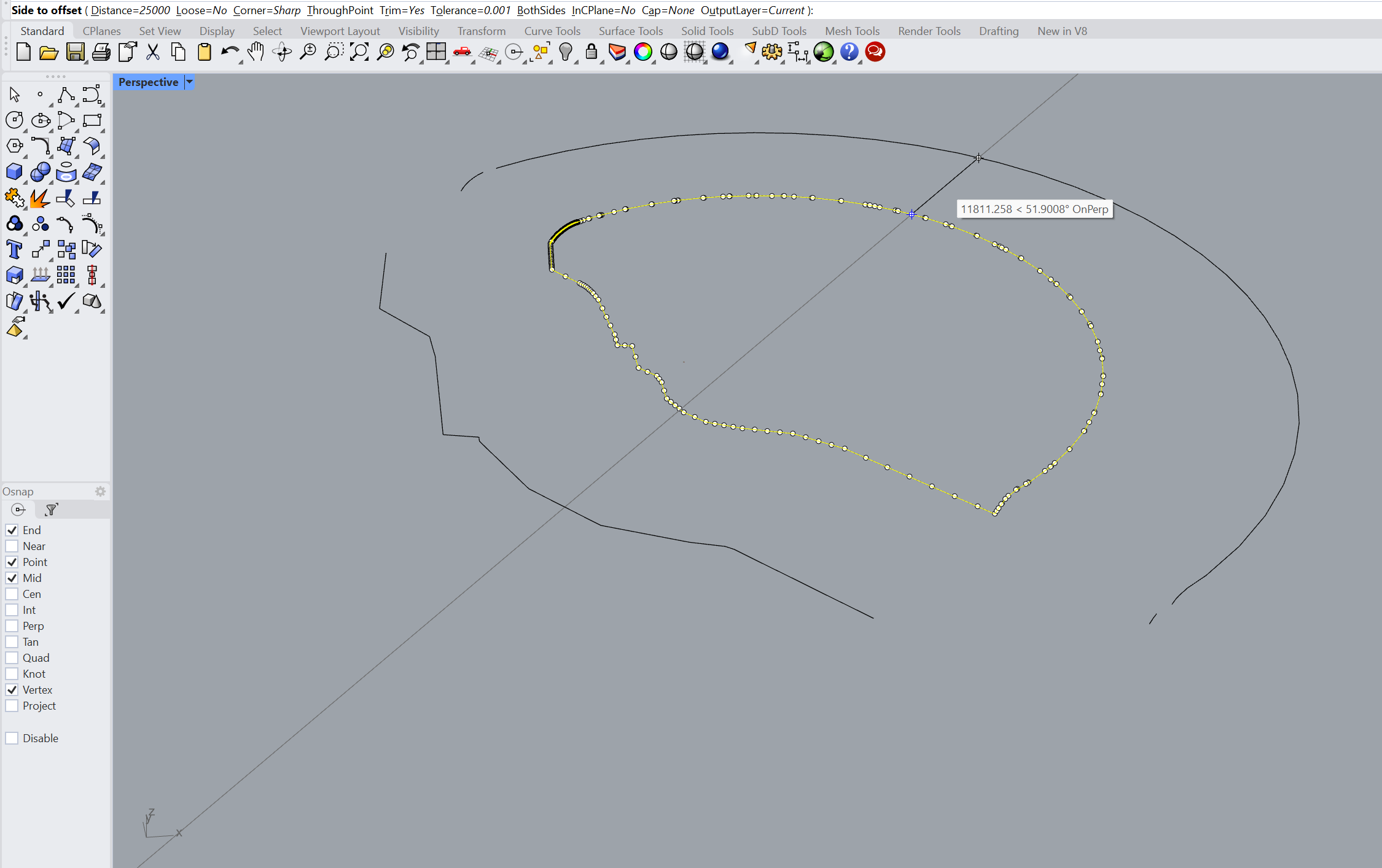
Now, the objective is to use the Offset command to offset this curve in the outward direction. You can use the Distance definition to control by how much the curve will be offset.
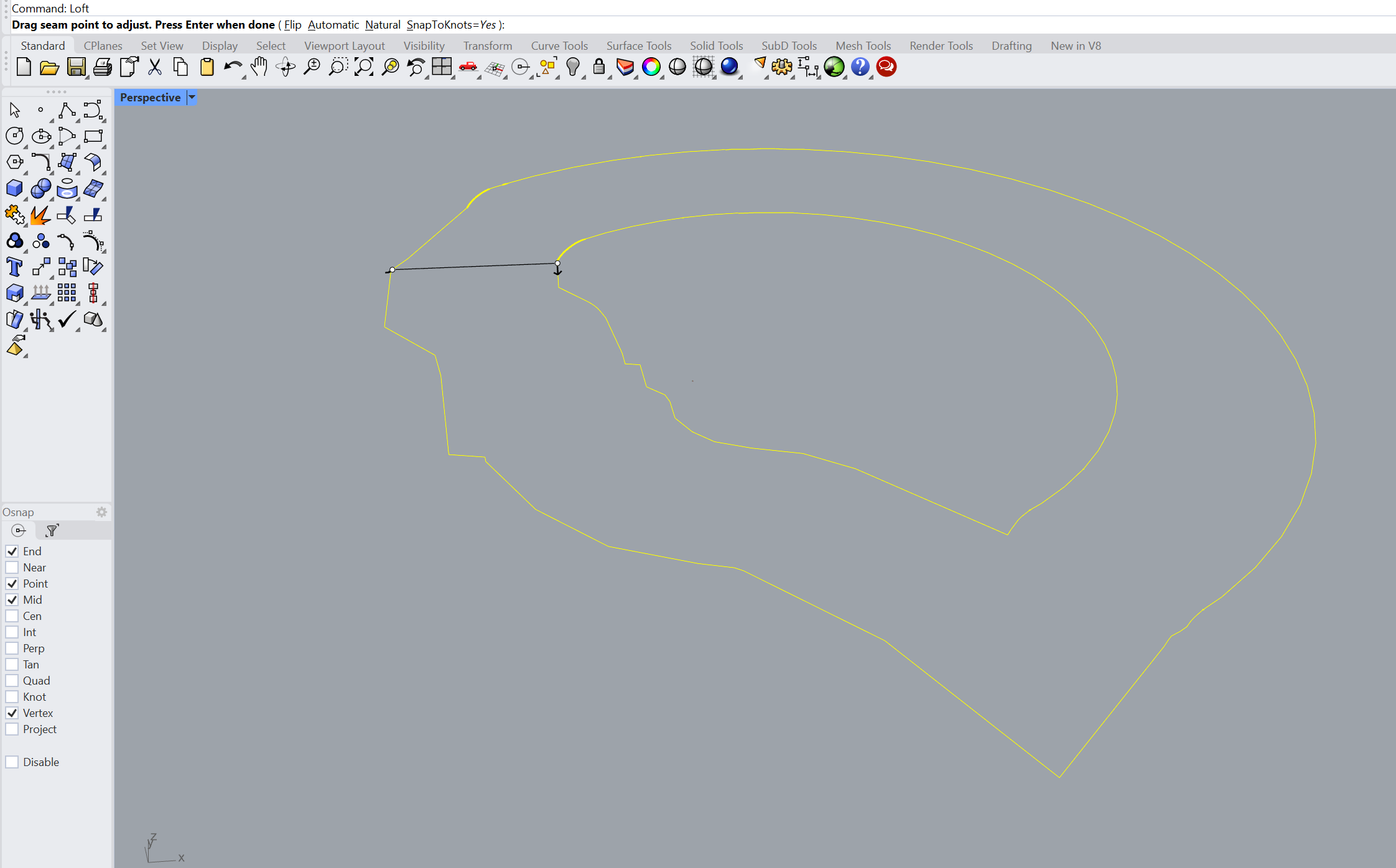
After the new curve is created, select the curves and run a Loft command:
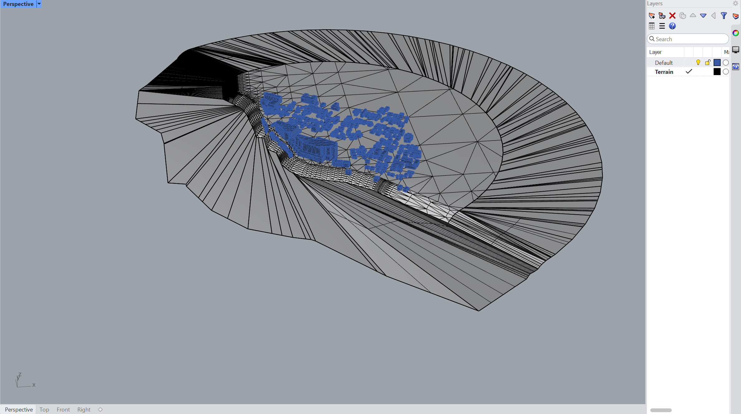
The figure below shows the resulting geometry with the extended terrain after the loft operation:
Note
If none of the above suggestions solved your problem, then please post the issue on our forum or contact us.


