In this article, we will present a feature available in SimScale that shows when and where divergence occurs within a simulation.
Approach
Computational Fluid Dynamics (CFD) simulations are highly iterative processes. In successful runs, the results converge to a final, stable solution. However, for several reasons, the solution may also diverge. When this happens, parameters within the domain can reach unphysical levels.
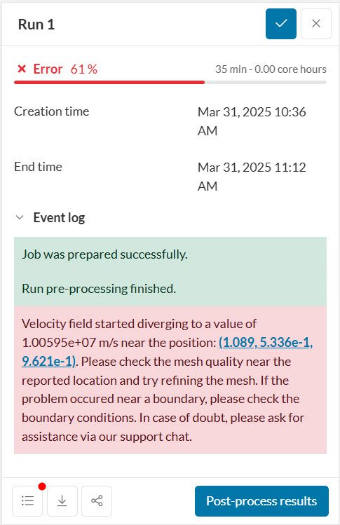
To help users identify and troubleshoot divergence in their simulations, SimScale has a divergence monitor. The following parameters are tracked: velocity, pressure, density, and temperature. Whenever a parameter reaches unphysical levels in the domain, the simulation automatically stops with an error message:
The error message above specifies which parameter diverged – the location within the CAD model where it happened may or may not be displayed. Depending on whether the location is displayed, there are two workflows possible to spot the problematic portions of the domain, and this is what we’re going to turn to next.
Troubleshooting
1. When Coordinates are Specified
To gain more insight into the causes of divergence, the following basic steps are useful:
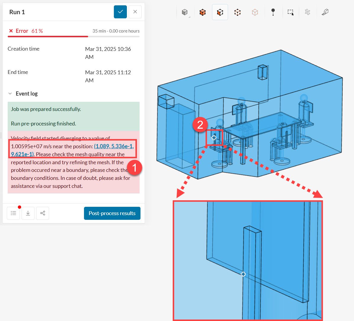
- Click on the coordinates displayed in the error message. In doing so, you will see exactly where the divergence occurred.
- If the point is close to one of the boundaries, double-check all boundary conditions, making sure they are correct.
- If the point is located inside the domain, inspect the mesh around the area. The mesh quality visualization feature is very useful in this step. Even just a few bad quality cells can create instabilities in the simulation, ultimately leading to divergence.
- If you do have bad cells, make sure to inspect the CAD model around the problematic region. Look for minute faces, very detailed topology, and small gaps. These can sometimes cause poor mesh quality.
Troubleshooting Example 1
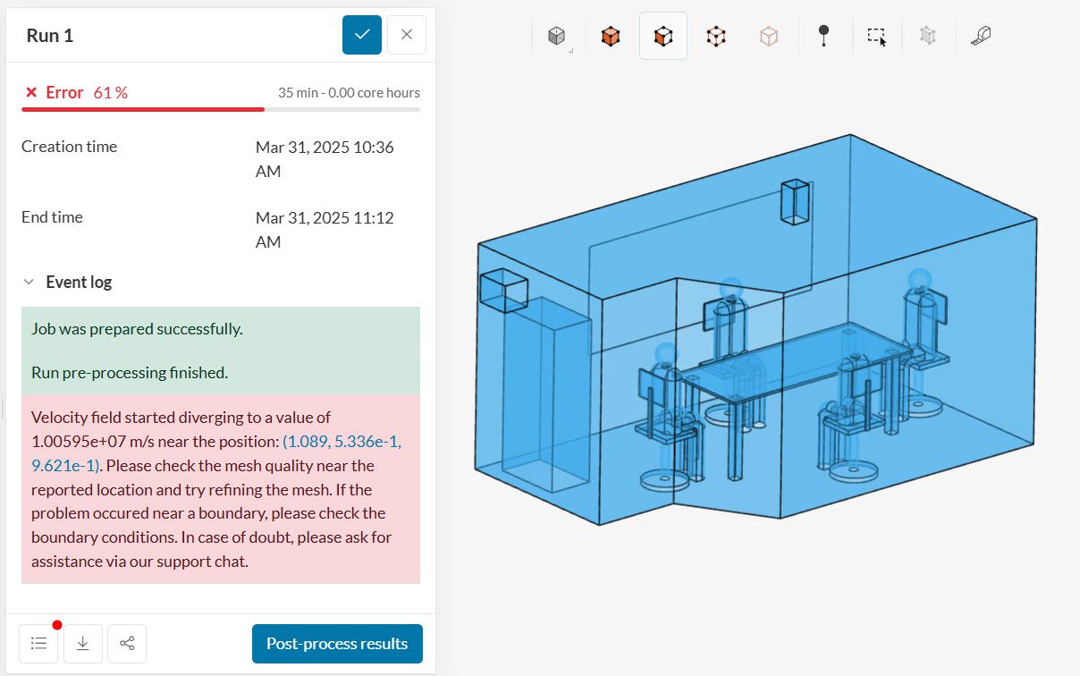
To illustrate the procedure, let’s go through an example. This is a case of internal convective heat transfer analysis of an office room. The monitor reports a divergence for the velocity field at a specific point within the domain:
By clicking on the coordinates displayed in the error message, we can see that the divergence started near the chair:
2. When Coordinates are not Specified
If no point coordinates are available, you should follow these steps for the troubleshooting:
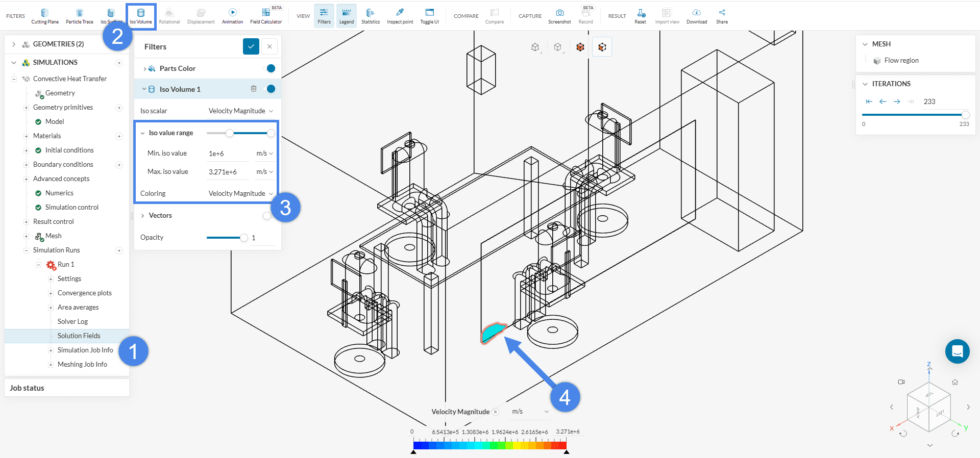
- Go to the Solution Fields for the failed run.
- In the post-processor, create an Iso Volume filter for the variable of interest.
- The upper limit can correspond to the highest value in the legend, while the lower limit can be adjusted downward from a high value until cell concentrations become visible.
- Inspect the mesh quality as explained in the previous example.
Troubleshooting Example 2
Using another diverging simulation from the meeting room, we can follow the outlined steps to identify the source of the divergence. For this new run, the Iso Volume filter reveals that the velocity field diverges around the window:
Mesh Quality Inspection
Upon clicking on ‘Mesh quality’, the post-processing environment opens. A very useful filter to spot bad cells is Iso Volume, the same one used for spotting the divergence when no point coordinates are displayed in the error message. By selecting a quality parameter and changing the minimum and maximum iso values, the bad cells are easily located all around the window area:
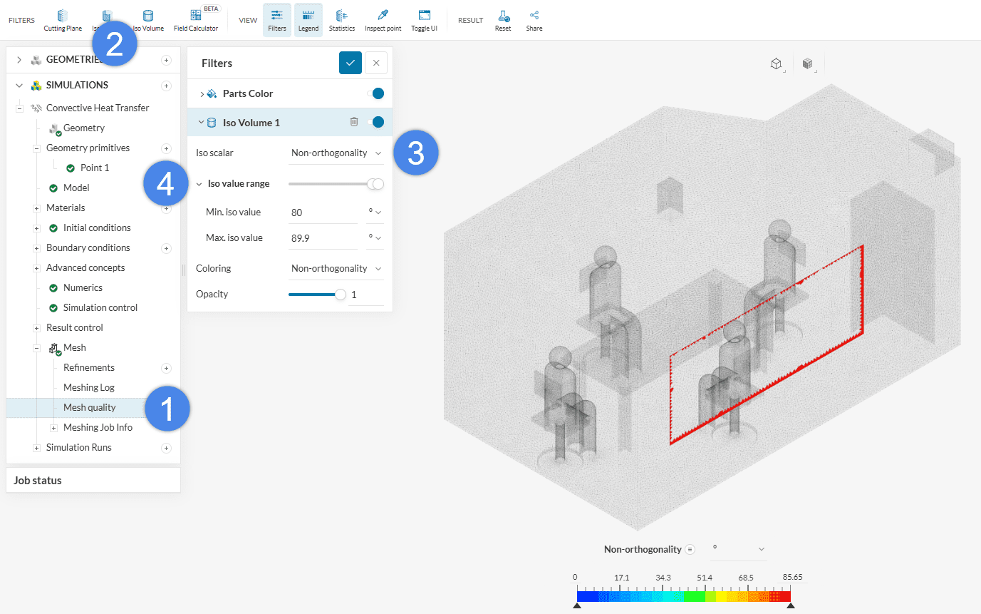
The mesh contains cells with up to 85.65 Non-orthogonality, which is too high (the recommended value is \( \ll \) 88). Furthermore, the location is the same as reported in the error message. In this case, two main workflows are possible:
- CAD clean-up around the problematic region. Refer to our CAD Edit documentation for more information
- Improving the mesh settings (for example, by applying additional local refinements, or improving the small feature suppression configuration).
In this case, zooming into the problematic region, we can spot a small face that seems to be causing the issue:
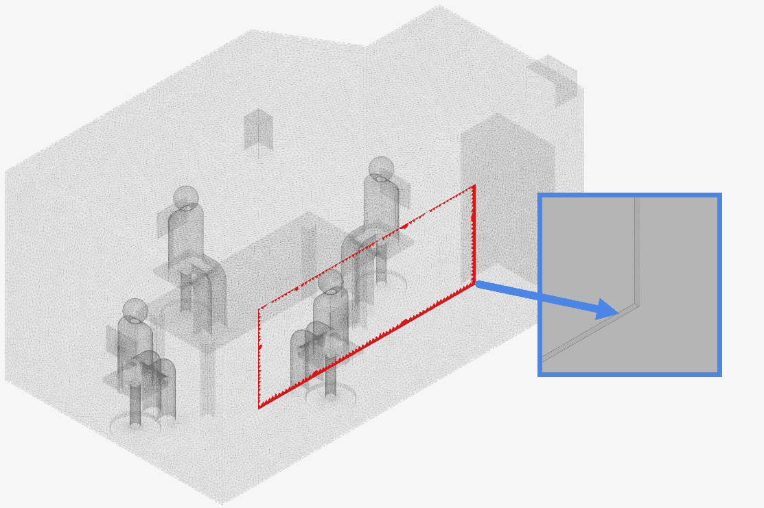
We could, for instance, remove it using a Delete face → Heal operation in CAD Edit on the original part (before generating the flow region).
Note
If none of the above suggestions solved your problem, then please post the issue on our forum or contact us.


