The article explains what the Atmospheric Boundary Layer is and how does the SimScale platform deals with complex geometries being intersected by it.
Atmospheric Boundary Layer
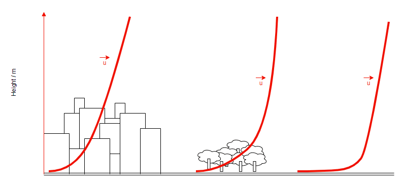
By definition, the Atmospheric Boundary Layer (ABL) is the lowest part of the troposphere and is directly influenced by the existence of the earth’s surface and responds to the surface roughness. Due to these factors, the wind conditions vary with the height and type of surface available.
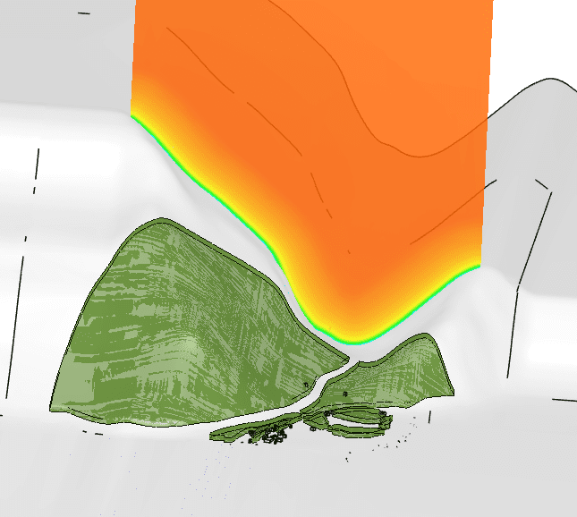
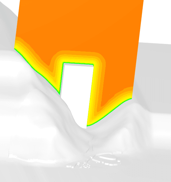
In Pacefish®\(^1\) Pedestrian Wind Comfort simulations, the ABL is automatically generated and takes into consideration the topography and the defined surface roughness. The ABL is generated on the limits of the flow domain. It follows the topology of the model, as shown in this example:
Different Wind Exposures
The ABL assumes the following values for the following conditions:
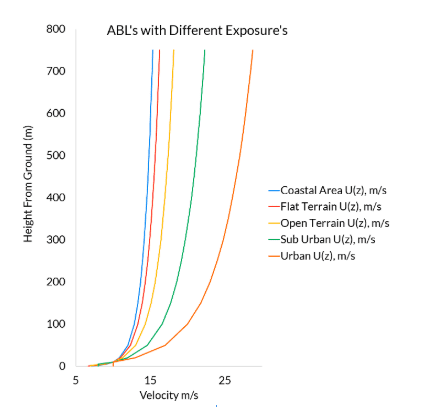
These types of terrains describe the areas we can find outside of the flow domain and influence the velocities that will be input into the ABL. As a consequence, generate different flow results on the region of interest.
When there is a need to apply extra roughness to the flow domain, the platform has a function that can be activated with the toggle, as demonstrated in the picture below.
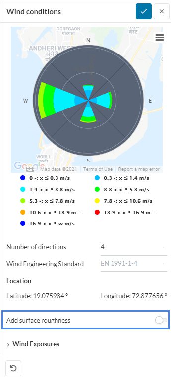
This added roughness is applied to the surface inside of the flow domain and outside of the region of interest. The conditions used to define the roughness are the ones previously used to define the ABL in the different directions of the model.
Recommendations When Using SimScale
As shown before, the ABL is generated by cutting the model on the limits of the flow domain. This means that if we have a part of the model crossing the flow domain that does not represent the topography or the ground level of the model, the ABL is applied to those faces and may influence the results of the simulation.
In the case of a building intersecting the flow domain, the ABL generated by the platform is applied on the roof and walls of that building.
For this reason, when preparing a model for simulation in SimScale, the buildings that intersect the flow domain should be removed from the model to avoid possible deviation from the correct result that might come from this intersection of the flow domain.
References


