Validation Case: Infinite Cylinder Subjected to a Volume Load
This validation case belongs to solid mechanics. In this case, an infinite cylinder is subjected to a voluminal load. The parameter being validated is:
- Volume load
SimScale simulation results were compared to the analytical solution presented in [SSLA100]\(^1\).
Geometry
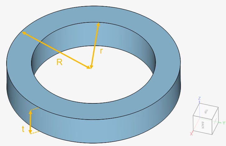
The geometry for this project consists of a slice of an annulus between two cylinders, as seen in Figure 1:
The dimensions of the geometry are given in Table 1:
| Geometry parameters | Dimension \([m]\) |
| Outer radius \((R)\) | 1.4 |
| Inner radius \((r)\) | 1 |
| Thickness of the slice \((t)\) | 0.5 |
Analysis Type and Mesh
Tool Type: Code_Aster
Analysis Type: Linear static
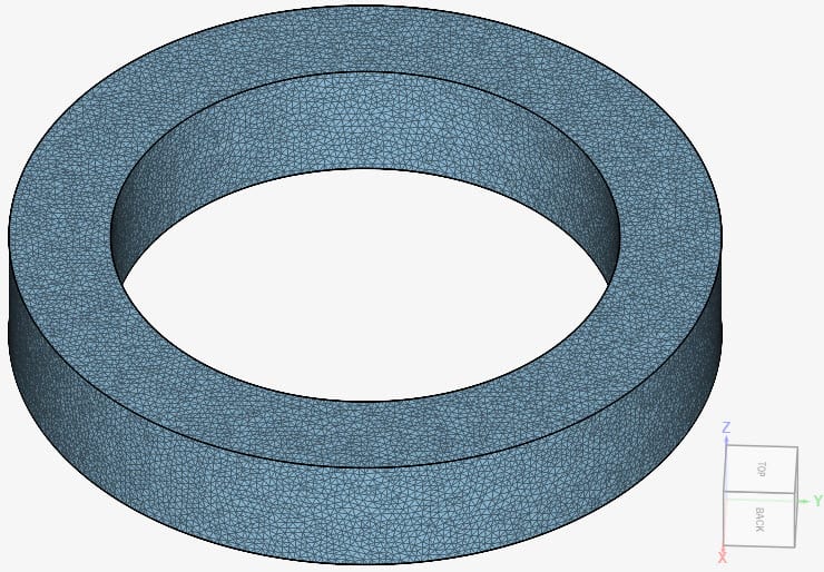
Mesh and Element Types: The mesh used in this case is a second-order mesh created in SimScale with the standard algorithm.
Table 2 contains details to the resulting mesh:
| Mesh Type | Nodes | Element Type |
| Second-order standard | 991445 | Standard |
Figure 2 shows the standard mesh used for this case:
Simulation Setup
Material:
- Material behavior: Linear elastic
- Young’s modulus \(E\) = 10 \(Pa\)
- Poisson’s ratio \(\nu\) = 0.3
- Density \(\rho\) = 1 \(kg/m³\)
Boundary Conditions:
The boundary conditions will be defined based on the following nomenclature:
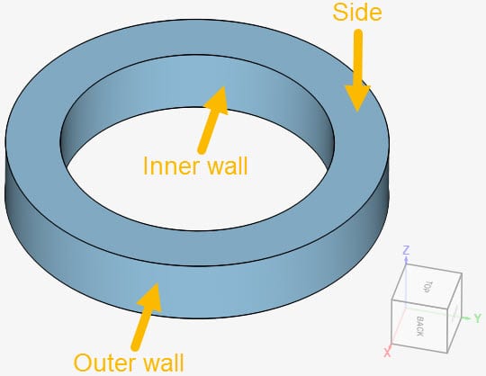
- Constraints
- \(d_z\) = 0 on both sides
- Isotropic elastic support applied to the inner wall, with a spring constant \(k\) = 0.001 \(N/m\). The purpose of this boundary condition is to avoid rigid body motion.
- Surface loads
- Pressure of 1 \(Pa\) applied to the inner wall
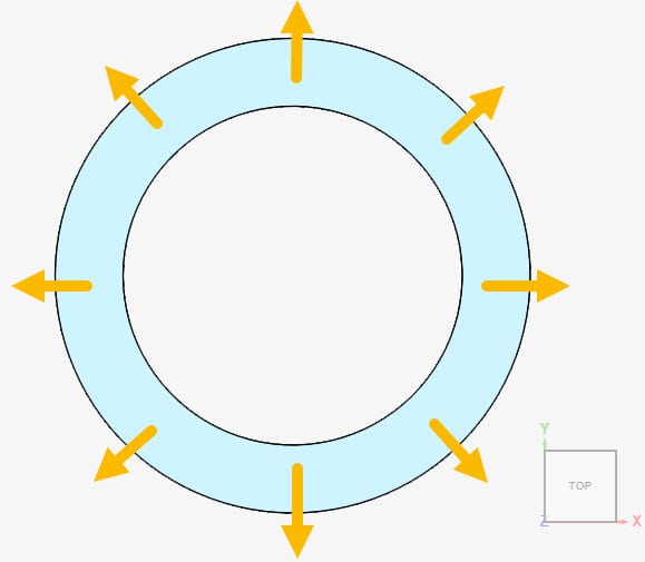
- Volume load applied in the radial direction, with a magnitude of \(\alpha r^2\ (\frac {N}{m^3})\), where \(\alpha = 1\ \frac {N}{m^5}\) and \(r\) is any given radius, in meters.
Note
Since the volume load is in cylindrical coordinates\(^1\), it was necessary to convert it to Cartesian coordinates using trigonometric functions. The resulting input formulae are:
$$Load_x = (x^2+y^2)cos(atan2(y,x)) \tag {1}$$
$$Load_y = (x^2+y^2)sin(atan2(y,x)) \tag {2}$$
$$Load_z = 0 \tag {3}$$
In equations 1 and 2, the \((x^2+y^2)\) term represents radius squared. The second part of the equations, consisting of trigonometric functions, is responsible for the conversion from cylindrical to Cartesian coordinates. As a result, the loads will be applied in a radial direction.
Result Comparison
The analytical solution for the displacements of the inner and outer wall are presented in [SSLA100]\(^1\). Find below a comparison between SimScale results and the analytical solution:
| Radius \([m]\) | Analytical displacement\(^1\) \([m]\) | Displacement – SimScale \([m]\) | Error [%] |
| 1 | 0.521309 | 0.521259 | -0.0096 |
| 1.4 | 0.442031 | 0.441986 | -0.0102 |
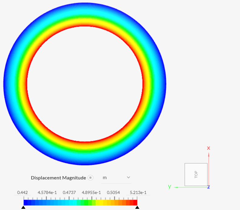
In Figure 5, we can see the resulting displacement contours. SimScale results show great agreement with the analytical solution.
Last updated: September 4th, 2023
Did this article solve your issue?
How can we do better?
We appreciate and value your feedback.


