Elastic Support
Elastic support can be used to introduce virtual springs on selected face nodes, thus constraining the body via springs. Figure 1 shows an elastic support boundary condition used in a sheet metal stamping simulation:
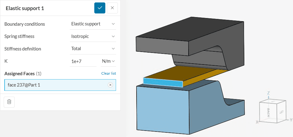
Each one of the possible inputs will be discussed below:
Spring Stiffness
Users can manually define specific stiffness for the springs. Two Spring stiffness criteria are offered in SimScale.
Isotropic
This option assumes the same spring stiffness in x, y, and z-directions. The figure below elaborates on the case. The numbers 1, 2, and 3 represent the deformations along the x, y, and z-directions, respectively.
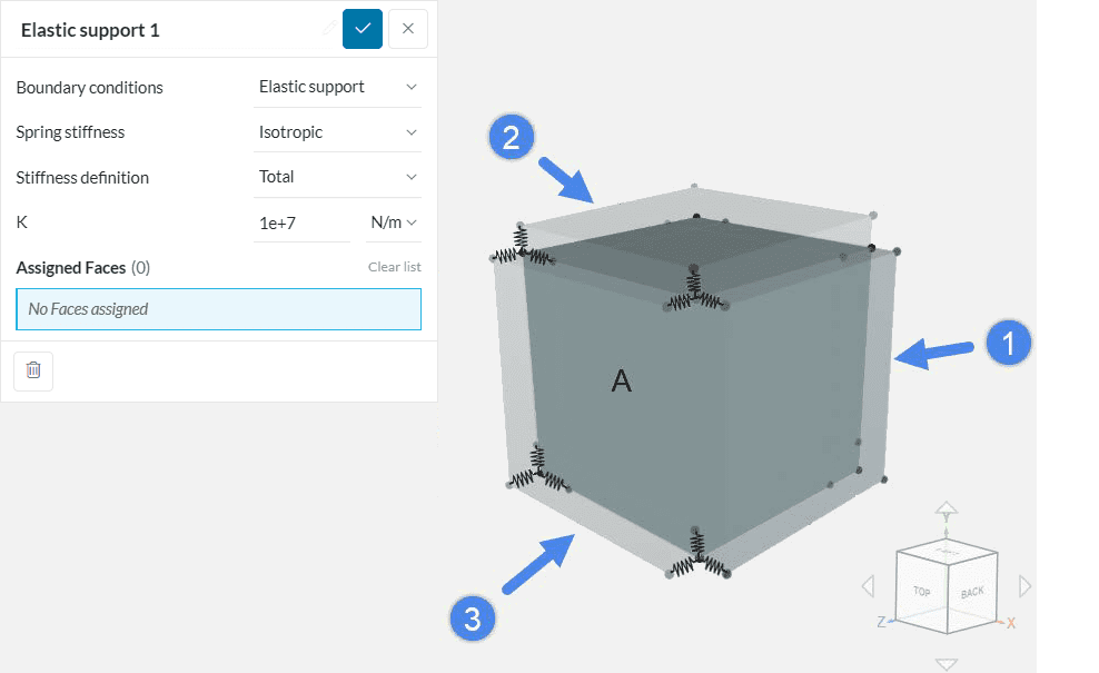
Springs as shown in Figure 2 are grounded to the nodes. Therefore, in the undeformed state, the moving ends of the springs remain on the nodes to which they are grounded.
After the application of load/displacement, the springs along that direction will react against the applied load/displacement. One can, therefore, use isotropic stiffness criteria if it’s required to constrain a geometry via specific spring stiffness in all directions.
Orthotropic
With Orthotropic, the user can define a different stiffness in each direction. The figure below elaborates on the case. Here, 1, 2, and 3 also represent deformations along the x, y, and z-directions, respectively.
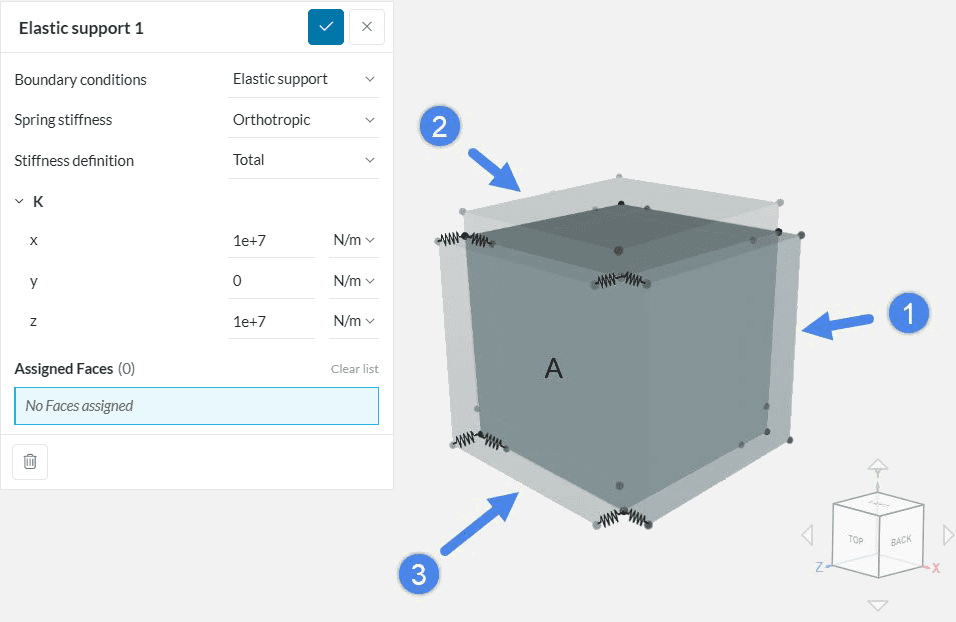
The grounding criteria for spring remains the same as discussed above. The only difference is that the spring will react only in the direction where a non-zero stiffness is defined.
Figure 3 shows that the body is unconstrained in the y-direction since zero stiffness was defined. Therefore, the orthotropic stiffness criterion is useful when constraining a geometry only in specific directions.
Stiffness Definition
Two types of Stiffness definitions are possible: Total and Distributed.
By selecting Total, the defined stiffness value is applied to all nodes of the face. With Distributed, the stiffness is distributed to the face area on which it is applied.
Please see the free vibrations on elastic support validation case for more information.
Applications of Elastic Support
There can be several applications of elastic support. Two cases are discussed below:
Replacing Physical Spring
Another application of elastic support is to replace a physical spring with a virtual one. By doing this, one can avoid complex spring structures in an assembly, saving computation time. Figure 4 shows an example.
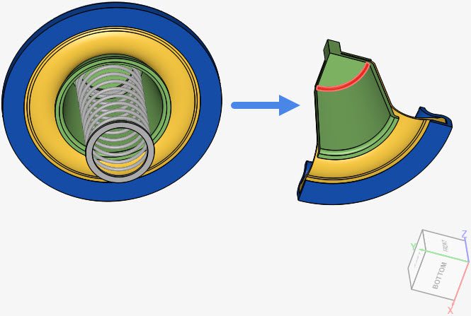
The figure above shows an example case of a pneumatic actuator. The left-hand side model is the complete geometry. On the right-hand side model, the physical spring is replaced by an elastic support applied to the face highlighted in red. Two things can be attained in this case:
- A complex spring structure is avoided.
- Only a quarter model is considered, due to symmetry, after the removal of the spring.
Please see the Pneumatic actuator with spring and elastic support project for more information.
Constraining Rigid Body Motion
In some of the analysis cases, a part of an assembly needs to be set free to perform a specific behavior. If one of the parts in an assembly is completely unconstrained, then a rigid body motion will likely take place at the start of the simulation. As a result of the free body motion, the solution matrix will diverge, leading to a failed simulation or very high residuals.
This often occurs when one tries to perform an analysis including physical contact between two parts of an assembly. If either one or both parts are kept unconstrained before the contact takes place, this will lead to a diverged solution. In such cases, the unconstrained body can be held by springs with a very low stiffness at the start of the simulation, to prevent the rigid body motion behavior.
One example of this application is shown in Figure 1 from this documentation page. The elastic support holds the sheet metal in place before the contact occurs. If no elastic support is specified, the sheet is free to move, leading to divergence.
Please check the Sheet Metal Stamping project for more details.
Optimizing the Spring Stiffness when Constraining Rigid Body Motion
When the objective of the elastic support is purely to constrain rigid body motion, then it is important that the chosen stiffness is:
- High enough to allow the simulation to run, and,
- Low enough so that the elastic support condition does not impact the simulation results
A typical workflow is to run the same simulation a few times with the same settings, only changing the elastic support definition. If the simulation fails due to rigid body motion, it means that the elastic support is still too low and should be increased by, for example, multiplying the stiffness by 10x each time. This process should continue until the first simulation is reached.
If the simulation is successful in the first attempt, then it is important to reduce the stiffness value and compare the results. In case the results are very close after changing the stiffness, then the elastic support is not greatly impacting the results. On the other hand, if the results do change greatly, then keep reducing the stiffness further and running tests, until the results stabilize.
Last updated: January 1st, 2026
Did this article solve your issue?
How can we do better?
We appreciate and value your feedback.


