Validation Case: Butterfly Valve
This validation case belongs to fluid dynamics and the aim of this case is to validate the following parameters inside a pipe with a butterfly valve:
- Pressure drop
- Torque
The simulation results of SimScale were compared to the results presented in the study done by Song, Xue Guan and Park, Young Chui with the title “Numerical Analysis of Butterfly Valve – Prediction of Flow Coefficient and Hydrodynamic Torque Coefficient“\(^1\).
Geometry
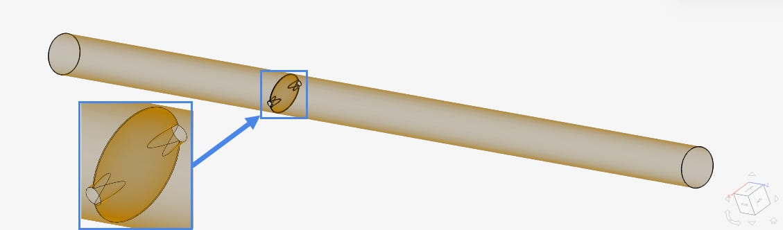
The model used in this validation case is a pipe with a discus-shaped butterfly valve inside, which can be seen below:
The dimensions of the pipe can be seen in the table below:
| Dimension | Value \([m]\) |
| Upstream length | 14.4 |
| Downstream length | 27 |
| Valve & pipe diameter (D) | 1.8 |
| Valve maximum thickness | 0.36 |
9 variants of valve opening angles ranging from 20° to 85° were used as a comparison to the reference study.
Analysis Type and Mesh
Tool Type: OpenFOAM®
Analysis Type: Steady state, Incompressible with K-Omega SST turbulence model
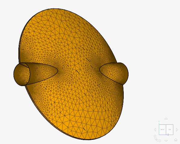
Mesh and Element Types:
The mesh was created with SimScale’s Standard mesher and the following table lists the details of the mesh:
| Mesh Type | Number of cells | Type |
| Standard | 6.4 Million | 3D Tetrahedral/Hexahedral |
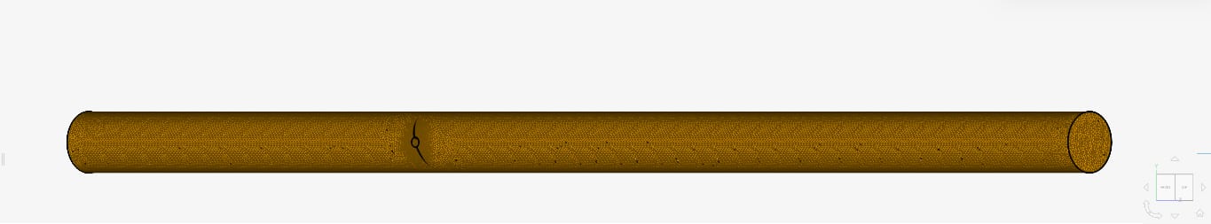
Furthermore, region refinements were also added in the area near the hinges of the valve so the calculation in those areas could be done accurately.
Simulation Setup
Fluid:
- Water
- Kinematic viscosity \((\nu)\): 9.338e-7 \(m^2/s\)
- Density \((\rho)\): 997.3 \(kg/m^3\)
Boundary Conditions:
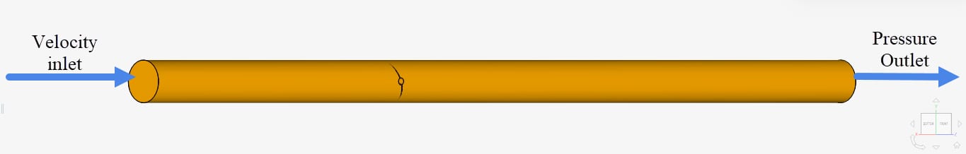
The boundary conditions are the same for all opening angles and were assigned as shown in Table 3:
| Boundary Condition | Value |
| Velocity inlet | 3 \(m/s\) |
| Pressure outlet | 0 \(Pa\) |
| No-slip wall | Pipe walls and valve surface |
Reference Solution
The reference solution for the flow coefficient and the torque coefficient is given in the following formulae:
Flow coefficient:
$$c_v = Q \sqrt{\frac{S_g}{\Delta P}}$$
where:
- \(c_v\): flow coefficient
- \(Q\): flow discharge \((GPM-Gallons\,per\,minute)\)
- \(\Delta P\): pressure drop \((psi)\)
- \(S_g\): specific gravity of water
Torque coefficient:
$$c_t = \frac{T(x)}{\Delta P \times d^3} \tag{2}$$
where:
- \(c_t\): torque coefficient
- \(T(x)\): torque in the x-axis \((N.m)\)
- \(\Delta P\): pressure drop \((psi)\)
- \(d\): diameter of pipe \((in)\)
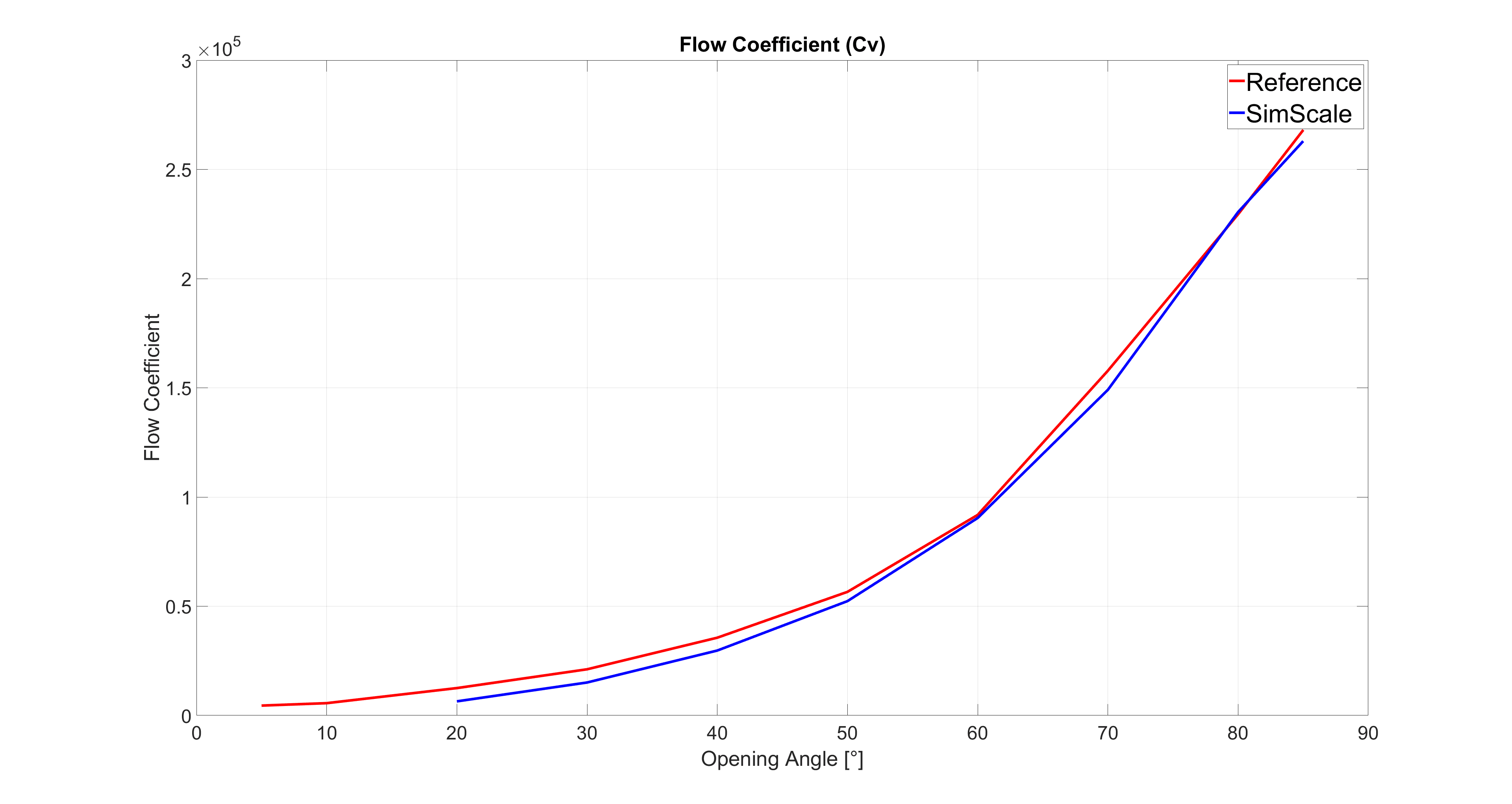
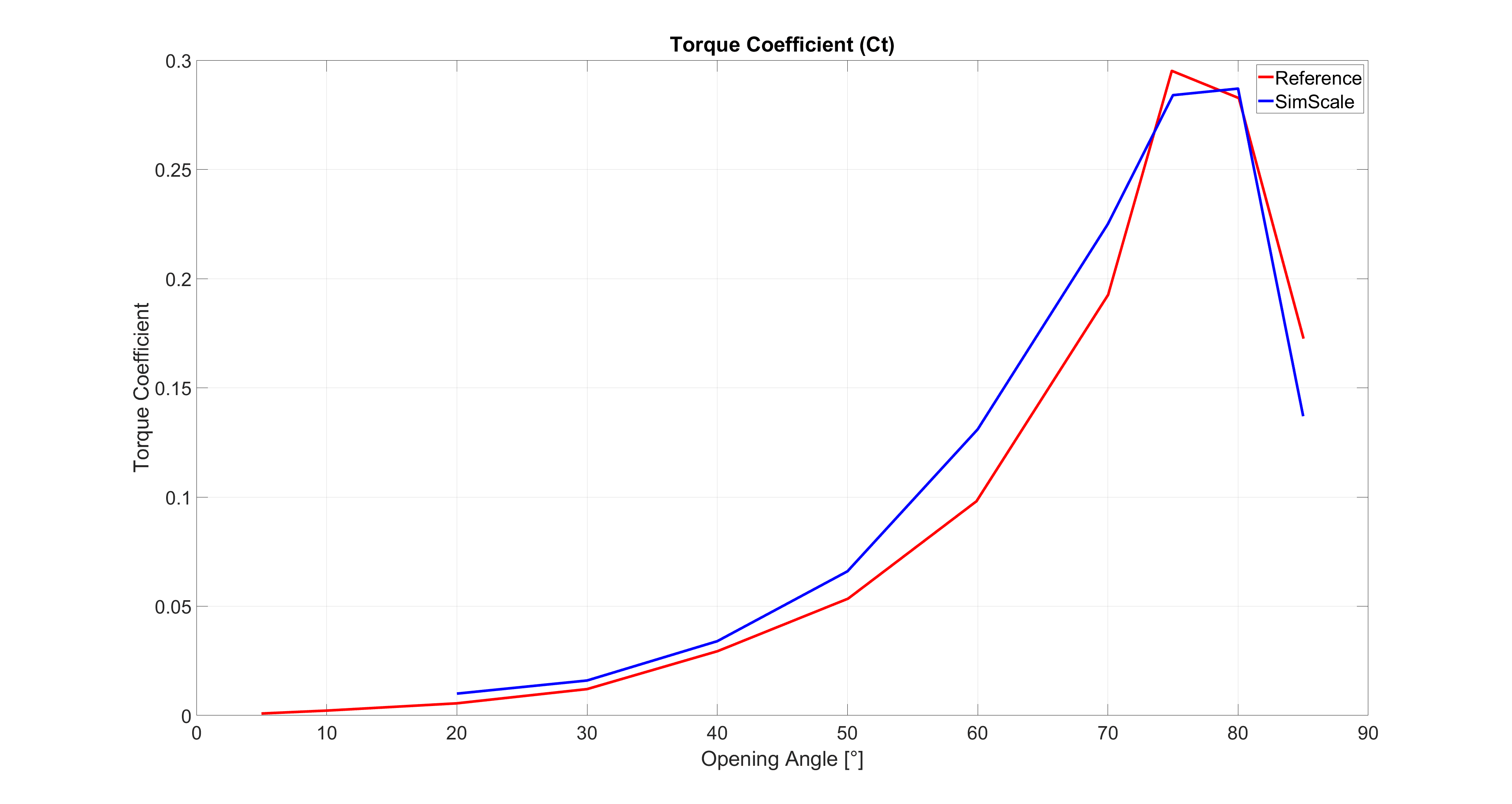
Result Comparison
Comparison of the flow and torque coefficients obtained from SimScale against the reference results obtained from [1] is given below:
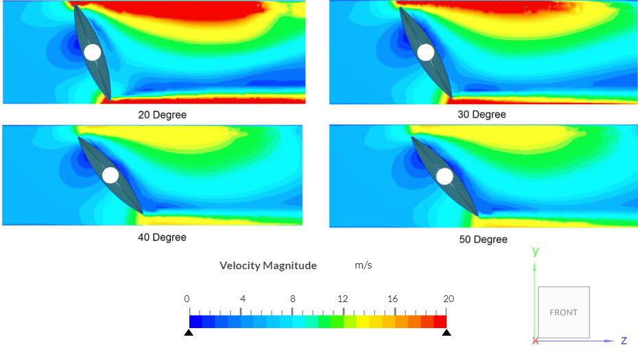
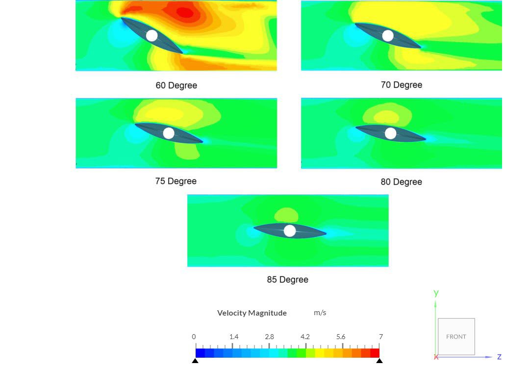
The flow contours inside the pipe when the valve is opened at the simulated opening angles as observed in our online post-processor:
Note
If you still encounter problems validating you simulation, then please post the issue on our forum or contact us.
Last updated: February 8th, 2026
Did this article solve your issue?
How can we do better?
We appreciate and value your feedback.


