Documentation
This validation case belongs to thermomechanics, with the case of a bimetallic strip under thermal load. The aim of this test case is to validate the following parameters:
The simulation results of SimScale were compared to theoretical computations derived from [Roark’s]\(^1\).
The geometry used for the case is as follows:
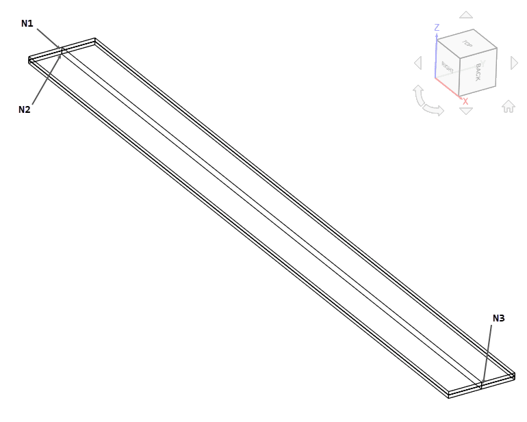
It represents a strip with length \(l\) of 10 \(m\), width \(w\) of 1 \(m\) and thickness \(t\) of 0.1 \(m\), composed of two strips each with thickness \(t_a , t_b\) of 0.05 \(m\). Nodes N1 and N3 are located at mid-thickness and node N2 is located at the bottom surface as shown in figure 1.
Tool Type: Code_Aster
Analysis Type: Thermomechanical steady state with static inertia effect
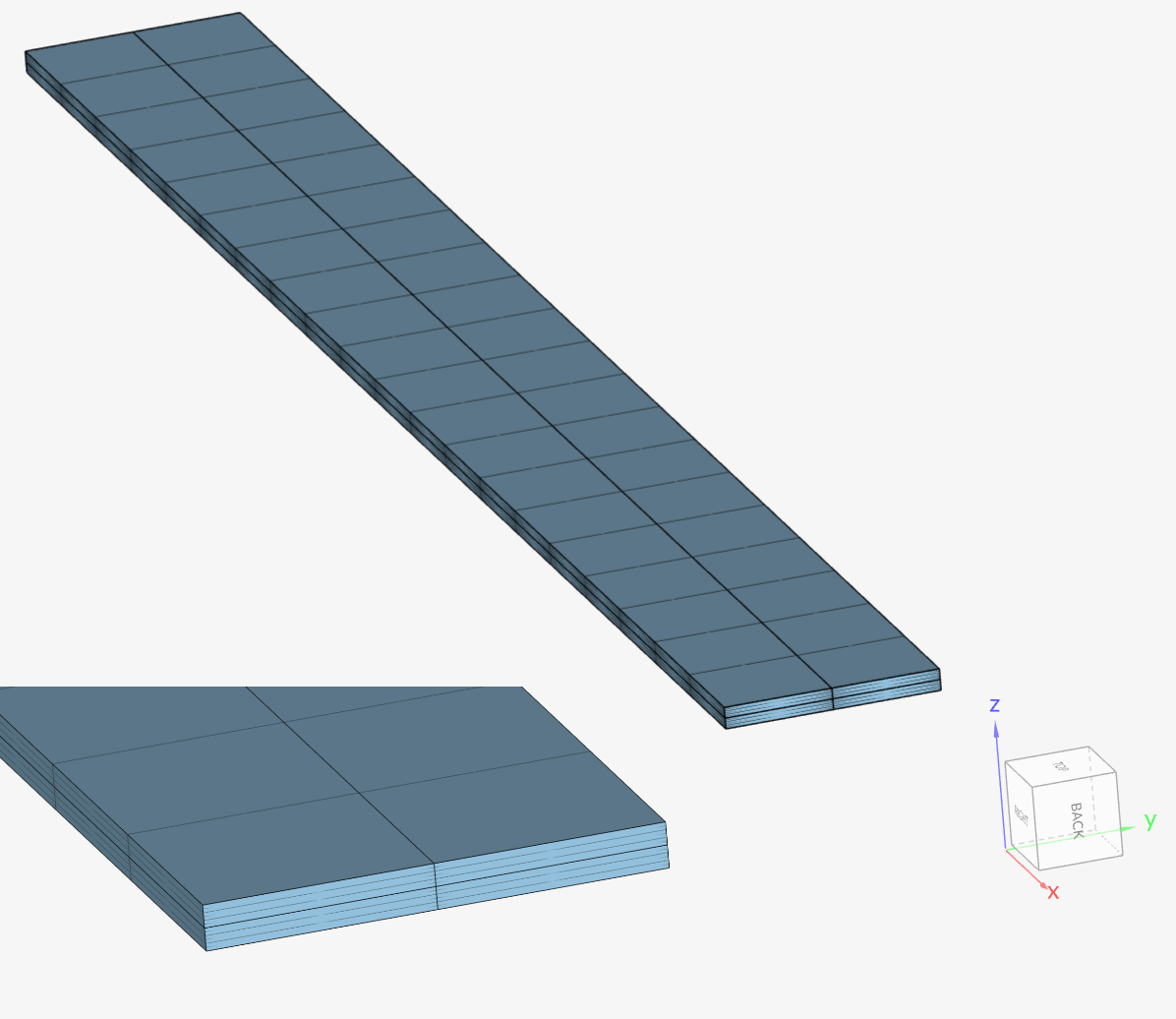
Mesh and Element Types:
| Mesh Type | Number of Nodes | Element Type |
|---|---|---|
| 2nd order hexahedral | 1698 | Standard |
The hexahedral mesh was created in SimScale with an extrusion mesh refinement.
Material:
Boundary Conditions:
The reference solution is of the analytical type, as presented in [Roark’s]\(^1\). It is given in terms of the displacements of the free end of the strip and the stress at the bottom surface:
$$ d_x = l (T – T_0) \frac{\gamma_a + \gamma_b}{2} $$
$$ d_z = \frac{ 3 l^2 (\gamma_b – \gamma_a) (T – T_0)(t_a + t_b) }{ t_b^2 K_1} $$
$$ \sigma_{bottom} = \frac{ (\gamma_b – \gamma_a)(T – T_0) E_b }{ K_1 } \Big[ 3 \frac{t_a}{t_b} + 2 – \frac{E_a}{E_b} \Big( \frac{t_a}{t_b} \Big)^3 \Big] $$
$$ K_1 = 4 + 6 \frac{t_a}{t_b} + 4 \Big( \frac{t_a}{t_b} \Big)^2 + \frac{E_a}{E_b} \Big( \frac{t_a}{t_b} \Big)^3 + \frac{E_b}{E_a} \frac{t_b}{t_a} $$
The computed solutions are:
\(d_x= 0.015\ m\)
\(d_z = 0.75\ m\)
\(\sigma_{bottom} = 50\ MPa\)
A comparison of displacements at point N3 and stress \(\sigma_{XX}\) at point N2 with theoretical solution is presented below:
| POINT | FIELD | COMPUTED | REF | ERROR |
|---|---|---|---|---|
| N3 | DX \([m]\) | 0.015 | 0.015 | 0.00 % |
| N3 | DZ \([m]\) | 0.7498 | 0.75 | -0.02 % |
| N2 | SIXX \([MPa]\) | 49.3092 | 50 | -1.38 % |
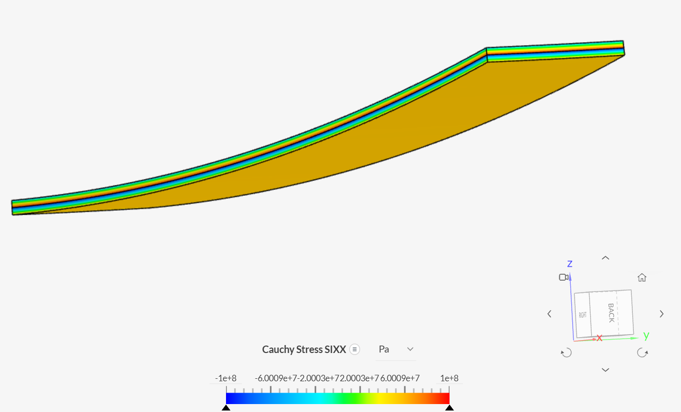
Illustration of the deformed shape and stress distribution on the bimetallic strip below:
Advanced Tutorial: Thermomechanical Analysis of an Engine Piston
References
Note
If you still encounter problems validating you simulation, then please post the issue on our forum or contact us.
Last updated: April 3rd, 2026
We appreciate and value your feedback.
Sign up for SimScale
and start simulating now


