Tutorial: Linear Static Analysis of a Crane
This article provides a step-by-step tutorial for a linear static analysis of a crane.
This tutorial teaches how to:
- Set up and run a linear static analysis of a crane.
- Assign boundary conditions, material, and other properties to the simulation.
- Mesh with the SimScale standard meshing algorithm.
We are following the typical SimScale workflow:
- Prepare the CAD model for the simulation.
- Set up the simulation.
- Create the mesh.
- Run the simulation and analyze the results.
1. Prepare the CAD Model and Select the Analysis Type
Firstly, click the button below. It will copy the tutorial project containing the geometry into your Workbench.
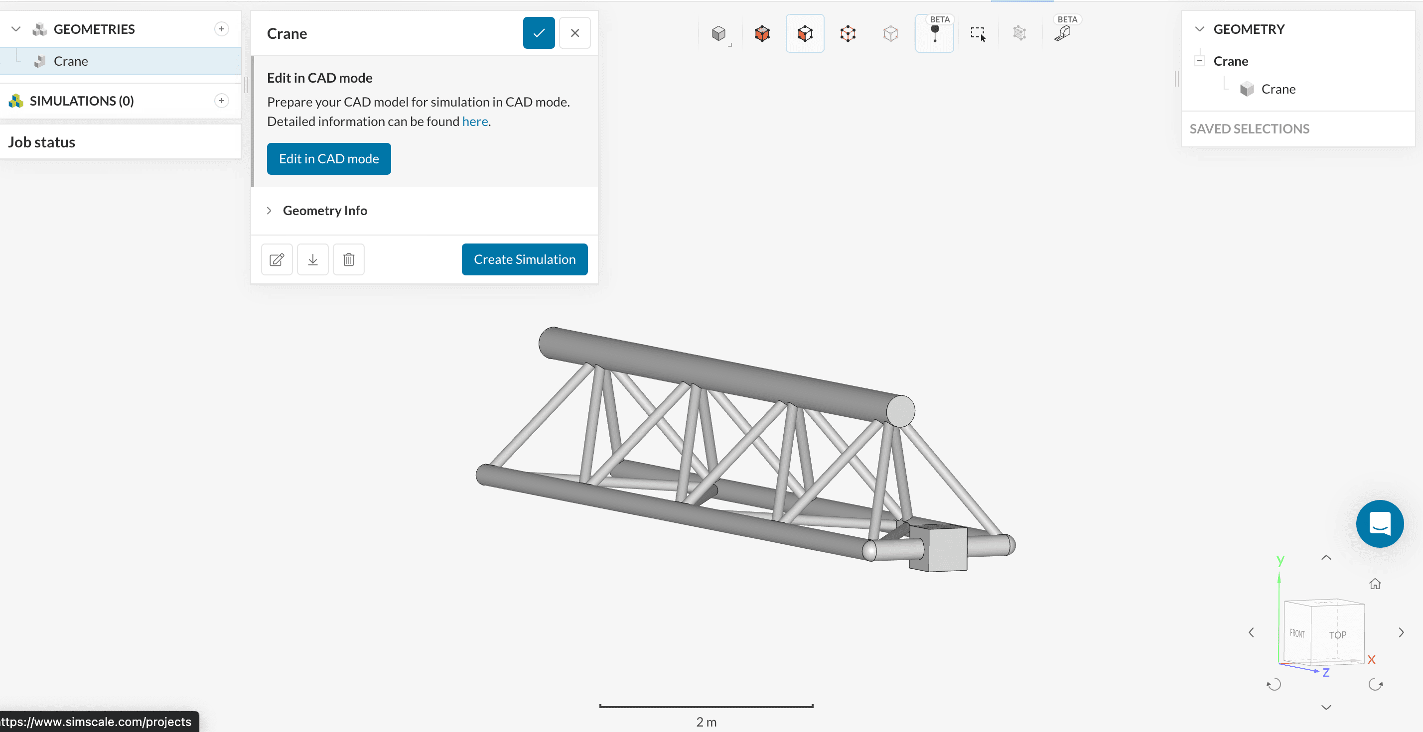
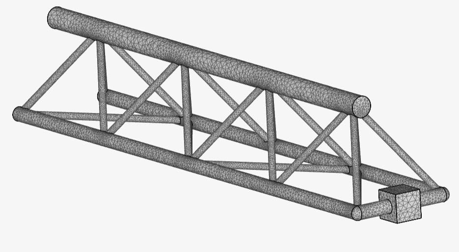
After that, the empty project will be imported into your Workbench. The following picture demonstrates what should be visible after importing the tutorial project.
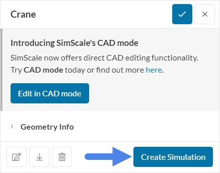
1.1 Create the Simulation
Firstly, you can create a new simulation by clicking the ‘Create Simulation’ button in the geometry dialog box.
At this point, the simulation type widget will pop up:
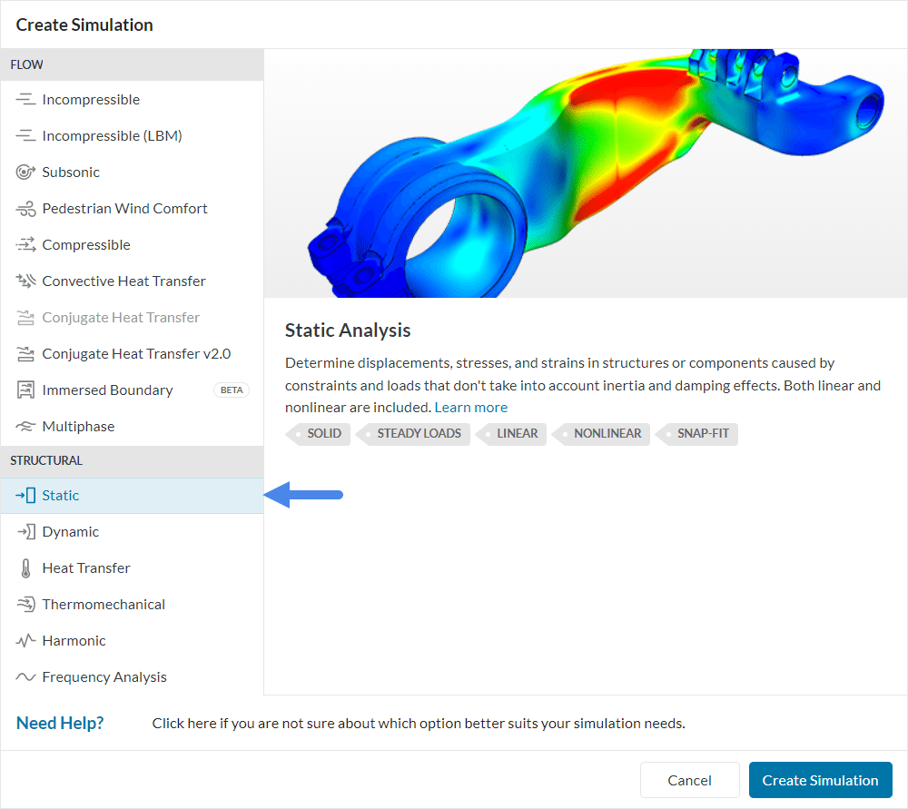
We will select the ‘Static’ analysis type for this simulation.
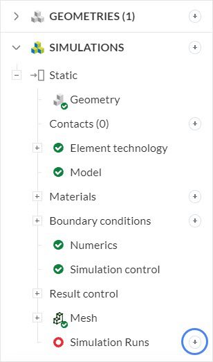
After selecting the analysis type, the simulation tree will appear. This shows you the settings that we will need to define before starting a new simulation.
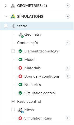
Now, you are ready to set up the linear static analysis of the crane model.
2. Simulation Settings
Before running the simulation, we will need to define the following important settings:
- Direction of gravity
- Material of the crane
- Boundary conditions
2.1 Direction of Gravity
The magnitude and direction of gravity highly affect the result of the simulation, because the crane’s weight is a noticeable load already. You can define the magnitude and direction of gravity by clicking on ‘Model’ in the simulation tree.
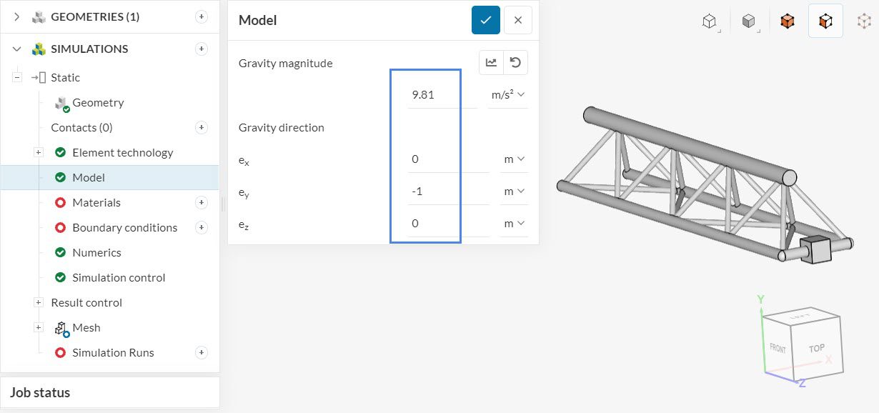
In this case, the Gravity magnitude is 9.81 \(m/s^2\) and the Gravity direction is in the negative y-direction.
2.2 Define a Material
You will also need to define the material of your crane. You can choose a material by clicking on ‘Materials’ in the simulation tree. The solid materials library opens, as in the image below:
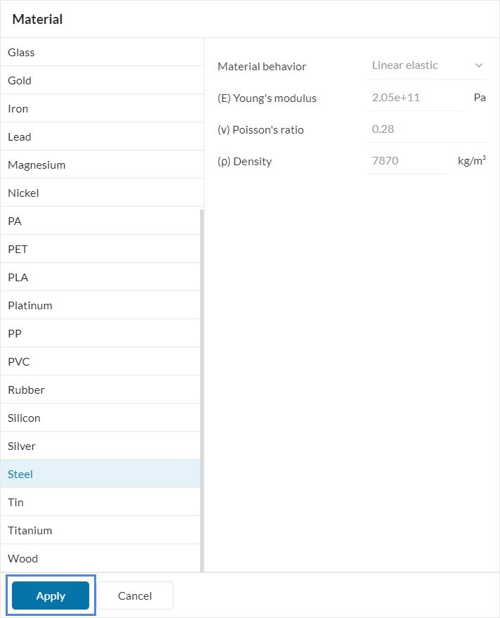
For this simulation, please select ‘Steel’ and confirm by pressing ‘Apply’.
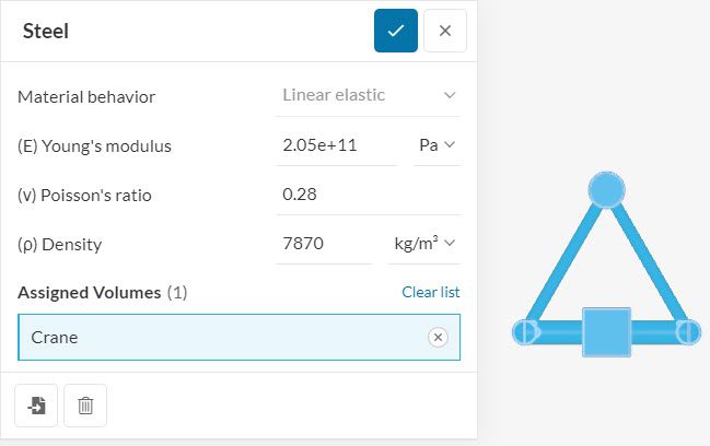
Since this geometry contains a single volume, the crane is automatically assigned to the material. You can proceed by clicking on the check icon to save. It is worth noting that you can define a custom material by changing the material properties, and it’s also possible to give a new name to your material.
2.3 Assign the Boundary Conditions
Boundary conditions play a key role in simulations – They define the physical conditions that you want to analyze in your design. In this simulation, we will apply fixed support and force boundary conditions. The image below provides an overview of the physics:
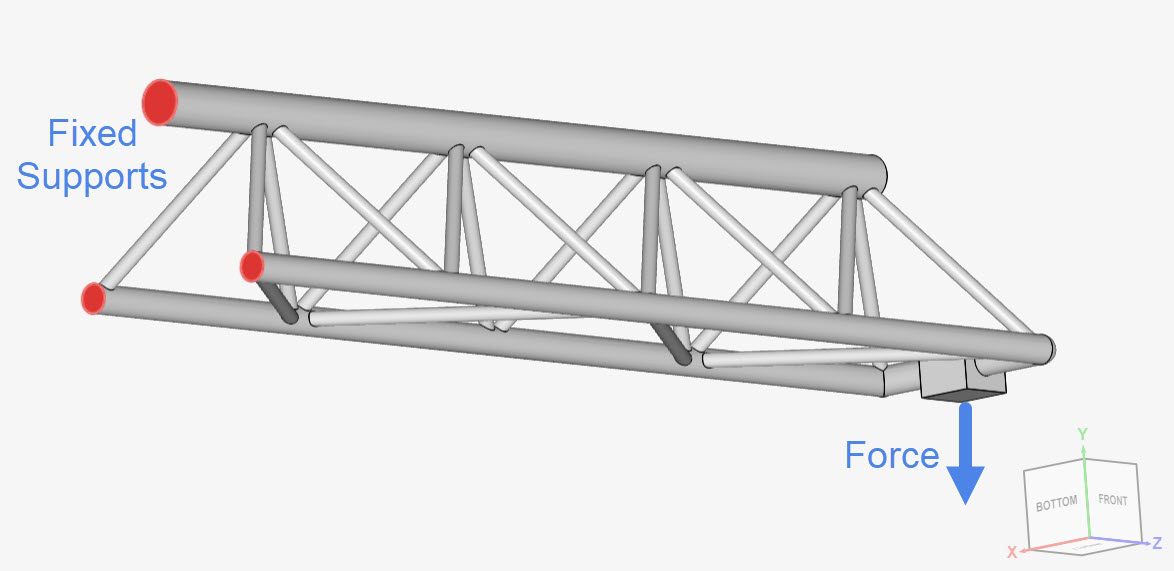
The next steps will show you how to assign each boundary condition.
a. Fixed Support
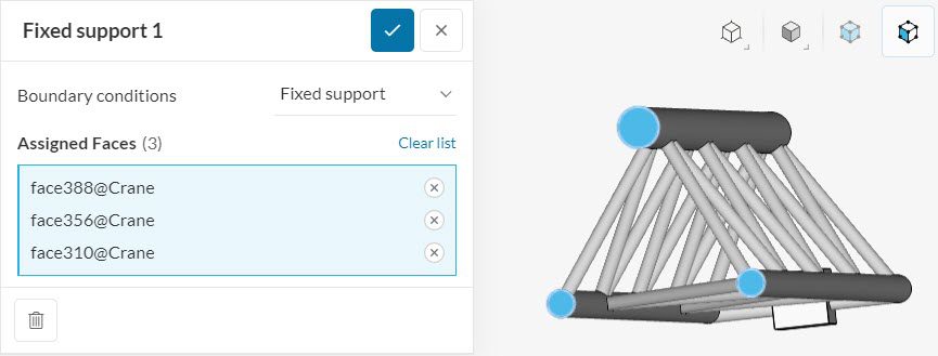
Firstly, you can define a new boundary condition by clicking on the ‘+ button’ next to Boundary conditions. A list shows up with multiple options – choose ‘Fixed support’ for the first boundary condition.

After that, a dialog box of the fixed support boundary condition will show up. Here, you will only need to assign the fixed support faces.
b. Force
Follow the same steps, this time create a ‘Force’ boundary condition.
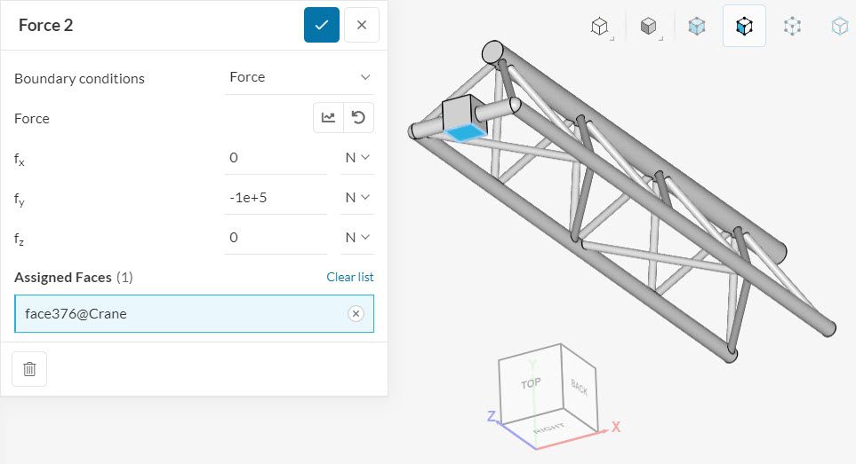
We will define our force to be -1e5 N in the y-direction, observing the orientation cube.
Note
No changes were made for the Numerics and Result control settings for this tutorial as default settings will be sufficient.
3. Mesh
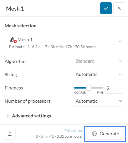
To create the mesh, we will use the standard algorithm, which is automated and delivers good results for most geometries.
No changes in the default settings are needed. For linear static simulations, SimScale creates 2nd order meshes by default, which increases the accuracy of the analysis.
Why 2nd Order Elements?
Here is an article on why 2nd-order elements are recommended and which finite element type you should use: Which type of finite element should I use?
Furthermore, the order of a mesh can be defined under the element technology tab.
The resulting mesh looks like this:
Related Meshing Knowledge Base Articles
Here are additional knowledge base articles that you can read regarding meshing:
4. Start the Simulation
You can start a simulation run by clicking on the ‘+ button’ next to Simulation runs.
At this point, you will be shown a dialog box containing an estimate of the computing resource that will be spent to run your simulation. You can proceed by pressing ‘Start’.
5. Post-Processing
After the simulation run has finished computing, you can access the results by one of two methods:
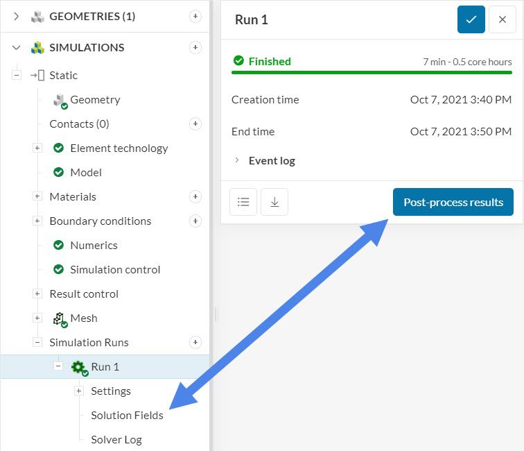
- Click on ‘Solution fields’ under the simulation run, or
- Click on the ‘Post-process results’ button in the run dialog.
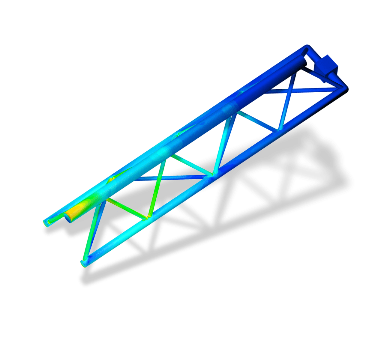
When you have been directed to the post-processor, you can start analyzing your results. For this tutorial, we will show the von Mises stress and the deformation of the crane.
5.1 Von Mises Stress
To analyze the von Mises stress on the crane structure, make sure that ‘von Mises Stress’ is defined under Parts Color:
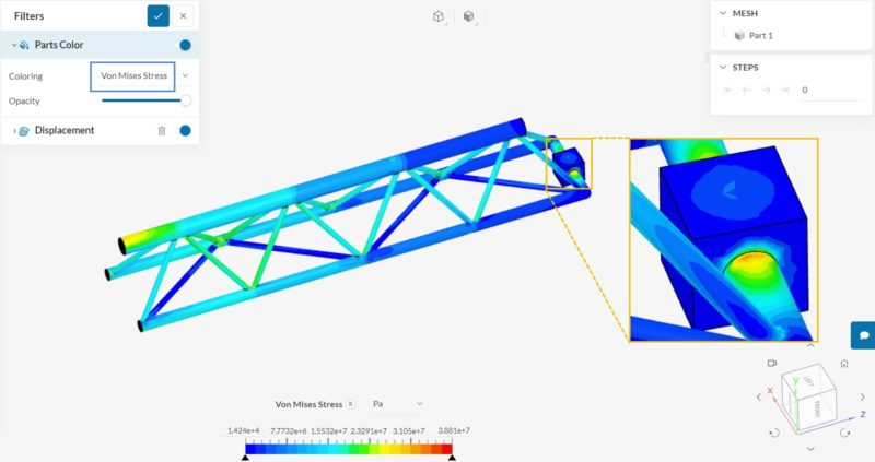
It can be seen that the highest stress levels occur close to the free end of the crane, where the force boundary condition is applied. There is also a high-stress region next to the top fixed support face.
5.2 Displacement
Since deformation is also important in stress analysis, we can visualize both the von Mises stress and displacement at the same time. The displacement settings can be changed under the Displacement filter:
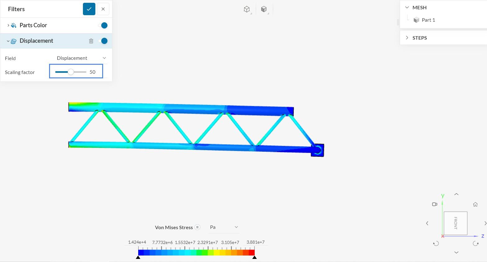
Since the displacements of the crane are very small, it’s possible to scale them up to obtain a better visualization. In the image above, the displacements have a Scaling factor of ’50’.
Now, to see the actual displacement values, we can also adjust the Parts Color to ‘Displacement Magnitude’:
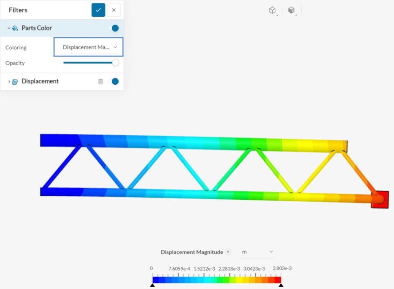
As expected, the free end of the crane undergoes the largest deformations, based on the initial position. The total maximum displacement due to the weight of the structure and the applied force is roughly 4 millimeters in this scenario.
Congratulations! You finished the tutorial!
Note
If you have questions or suggestions, please reach out either via the forum or contact us directly.
Last updated: September 18th, 2023
Did this article solve your issue?
How can we do better?
We appreciate and value your feedback.
What's Next
Tutorial about the Bending of an Aluminium Pipe

