Question
SimScale structural analysis uses exclusively solid 3D finite elements with a basic choice of either first order (4 nodes) or second order (10 nodes) tetrahedrals. Which type of finite element should I choose?
Note
Some additional, less frequently used finite elements are also available in SimScale but will not be discussed in this article.
Solution
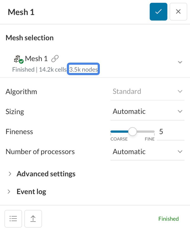
Second order elements are a type of finite element that capture the structural behavior more accurately but are computationally intensive due to the increased number of nodes. Users should note that when discussing meshes in FEA the number of nodes is the defining feature, not the number of cells. You can check the number of nodes in any of your generated meshes as shown below:
Generally, mesh sizes over a few million nodes should be avoided and you should aim to achieve mesh independent results with the least number of nodes possible so as to minimize computational cost. Mesh independence means that if the mesh fineness is reduced the results do not change significantly.
SimScale provides an automatic mesh technology based on the geometry, but the user can always set this up manually:
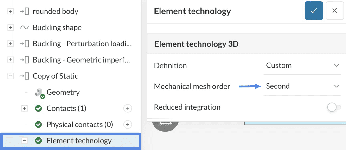
As shown by Figure 2, the user only needs to go to the Element technology tab on the simulation tree, and then select ‘Custom’ to allow the mesh order definition.
As a rule of thumb, second order elements should always be used when possible in order to maximize accuracy. Unfortunately, this is generally not the case for very large, complex geometries as the mesh size becomes too large with second order elements. For complex geometries, first order elements will have to be used. This can significantly reduce the accuracy of your simulation particularly when thin parts are present that undergo bending. When using first order elements you will need at least 3 elements through the thickness of all parts in order to produce results that reflect realistic bending.
Important Information
If none of the above suggestions did solve your problem, then please post the issue on our forum or contact us.


