In order to capture all necessary geometric details, adding mesh refinements can be of prime importance, especially if there are parts that are rather small in relation to the whole geometry or assembly. Also, regions, where physical effects need to be simulated well, need to have refinements. This includes the inlets and outlets of the flow domain.
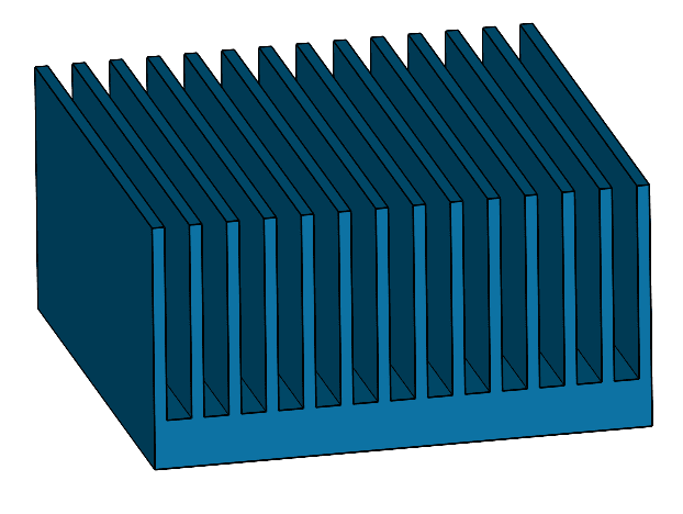
This article describes how to estimate the correct cell size before a mesh is generated on the example of a heat sink with thin ribs (although the approach is applicable for all types of geometries), as shown in the following figure:
Approach
You can get an impression of the dimensions of the geometry with the scale in the Workbench:
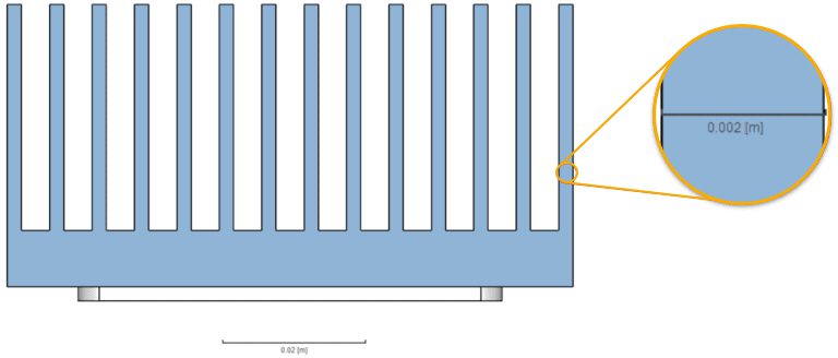
Zoom to the part you are interested in and measure its thickness, then divide it by the numbers of cells required to define the cell refinement. In this case, the ribs have a thickness of 0.002 \(m\).
Best Practices
For thin parts like the ribs of the heat sink, it is recommended to divide them into at least two to three cells. In this case, we divided them into seven parts using a hexahedral mesh.
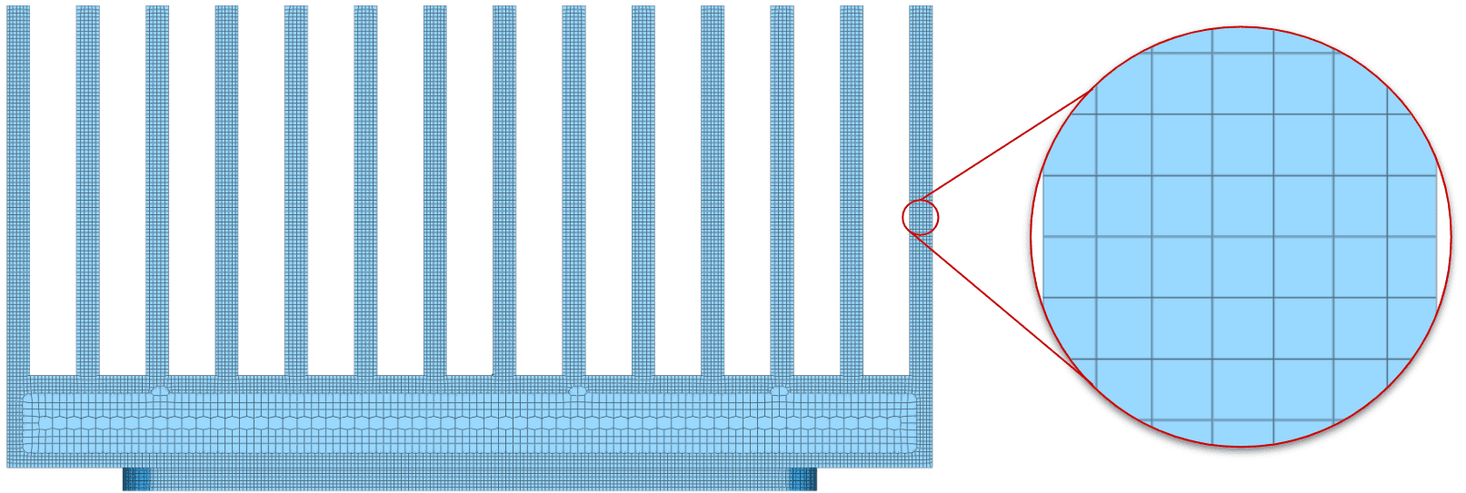
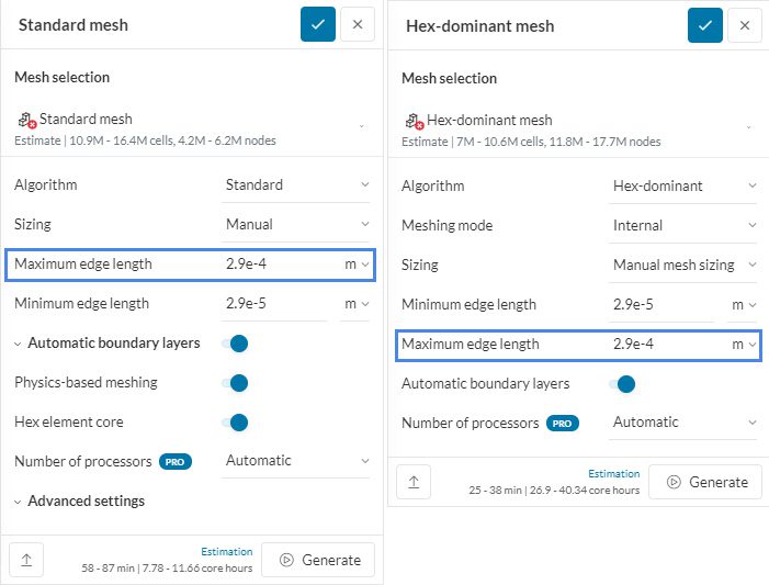
Accordingly, we need to divide the measured 0.002 \(m\) by 7 which leads to a cell size of approximately 0.00029 \(m\). Now, you can specify this value as the maximum cell edge length under Region refinement and add a cartesian box geometry primitive perfectly surrounding the ribs section for either the standard mesher or the hex-dominant mesher.
You can also do this under global mesh settings but then it would apply for the whole CAD geometry rather than a specific region of interest leading to a finer mesh overall.
One should note that the generated mesh need not be a structured mesh and hence the cell distribution and size will not be uniform and hugely depends on the geometry features and the type of cell elements i.e. tetrahedral, hexahedral or both.
Gap refinement factor
The above-discussed approach is more of a logical breakdown of mesh cell size control using simple math division and is applicable to any section of the CAD model.
SimScale’s standard mesher also provides a dedicated feature to better capture small gaps in the model by controlling the cell distribution to some extent. For example, the air between the fins of a heat-sink or even the solid heat-sink fins themselves. Read more on that here.
Note
If none of the above suggestions solved your problem, then please post the issue on our forum or contact us.


