Point Mass
With the Point mass boundary condition, a remotely concentrated mass and inertia can be created and connected to specific faces.
The parameters of the boundary condition to be defined are:
- Mass: Total mass to be applied in the lumped model, in units of \(kg\) or \(lb\)
- Mass moment of inertia: Rotational inertia in units of \(kg·m^2\) or \(lb·in^2\), assumed to be expressed in the components of the global coordinate system and centered on the External point. The mass moment of inertia is not defined in static and linear thermomechanical analyses.
- External point: Here the user defines the coordinates of the center of mass, where all the modeled material is assumed to be lumped. The coordinates are given in the global coordinate system of the model.
- Deformation behavior: This property defines if the assigned entities (i.e. those on which the point mass will be connected to) may deform, or if they are assumed to be rigid. When set to Deformable, no additional stiffness is generated on the applied entities. When set to Undeformable, the entities behave like a rigid part. The connection between the remote point and assigned entities is a multi-point constraint which blocks all relative displacements between the affected nodes.
- Enable search radius: Enable search radius places a sphere with a user-defined radius on the external point. Only the nodes from the assigned entities that are inside of the sphere will be associated with the point mass boundary condition. This is often useful when assigning large faces, as it allows the user to limit the number of remote point connections and, therefore, memory requirement.
- Assignment: Set of faces or volumes where the remote point mass will be connected.
Hint
If the deformable option is used and the number of nodes on the assigned entities is large (>1000), it is advised to use either the MUMPS or PETSC solver instead of Multfront since the performance of Multfront is not optimal for this kind of equations.
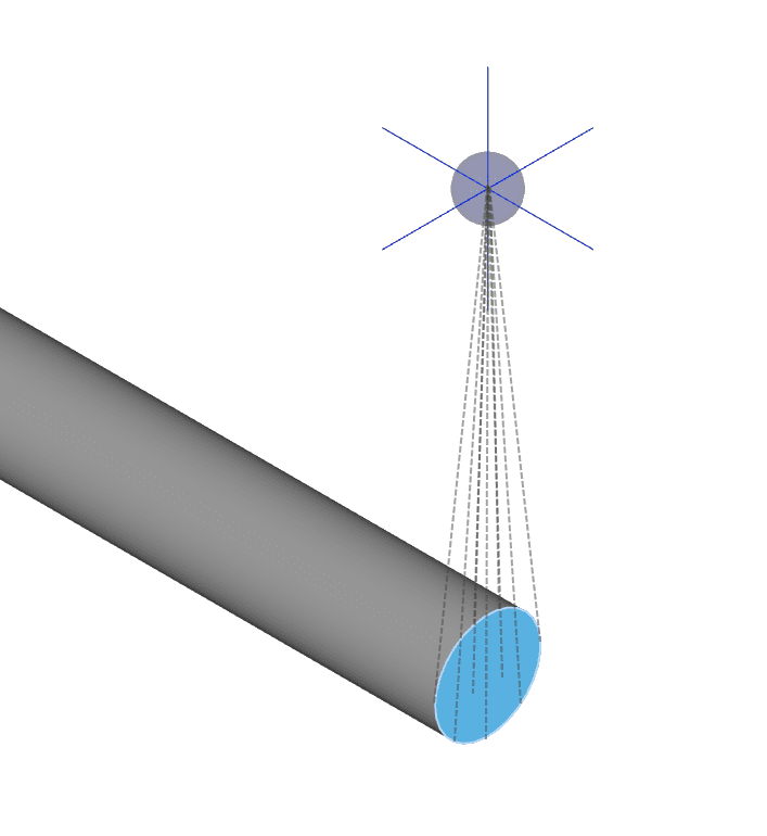
Following is a schematic for a point mass created using the boundary condition. The location is represented by the spherical glyph. The mass is remotely connected to the end face of the beam, highlighted in blue, through elements represented by the dashed lines. As a result, the weight of the point mass is supported by the beam through the end face.
Supported Analysis Types
The following analysis types support the usage of this boundary condition:
Remote Connections and Deformation Behavior
For more details on the remote connections and the deformation behavior of this boundary condition, please refer to the corresponding sections of the Remote Displacement boundary condition documentation page.
Computing the Properties
The overall goal of this boundary condition is to replace the effect of connected parts in a model. By using this approach, the simulation can be focused on a smaller set of parts, optimizing simulation resources. Some examples of such effects can be:
- Weight of the connected part
- Inertia of the part in dynamic simulations (transient or harmonic)
- Effect of the inertia of the connected part on natural vibration frequencies and shapes
- Large mass method to impose accelerations indirectly
The inertial properties of the replaced parts are typically obtained in the CAD program used to create the model. It is important that the global coordinates system is used to compute the coordinates of the center of mass, and that it is not changed before importing the part into SimScale. Also, note that the mass moments of inertia is expressed in a local coordinates system oriented with the global coordinates system, but located at the center of mass.
Related Documentation
- Remote displacement boundary condition
- Remote force boundary condition
- Validation case: Cantilever beam with off-center masses
Last updated: April 7th, 2025
Did this article solve your issue?
How can we do better?
We appreciate and value your feedback.


