Documentation
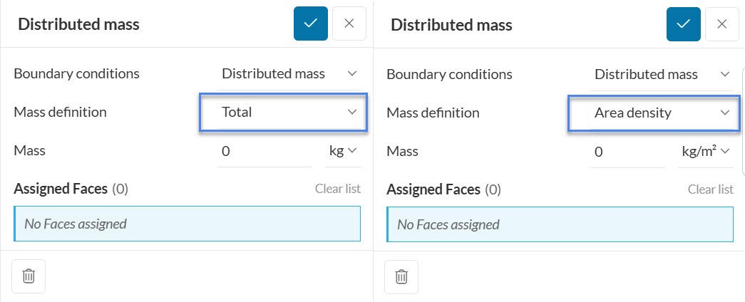
The Distributed Mass boundary condition enables the user to account for the mass distribution of secondary parts not geometrically added in the model, but which might still influence the kinematic behavior of the primary parts represented in the model. This is particularly useful in scenarions where additional mass needs to be accounted for in structural analysis. The extra mass will be applied over a surface and may be defined in two different ways:
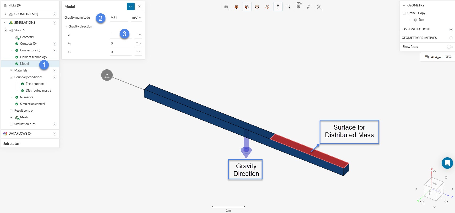
It is important to mention that, for this boundary condition to work properly, gravity needs to be defined in the correct direction.
The following analysis types support the usage of this boundary condition:
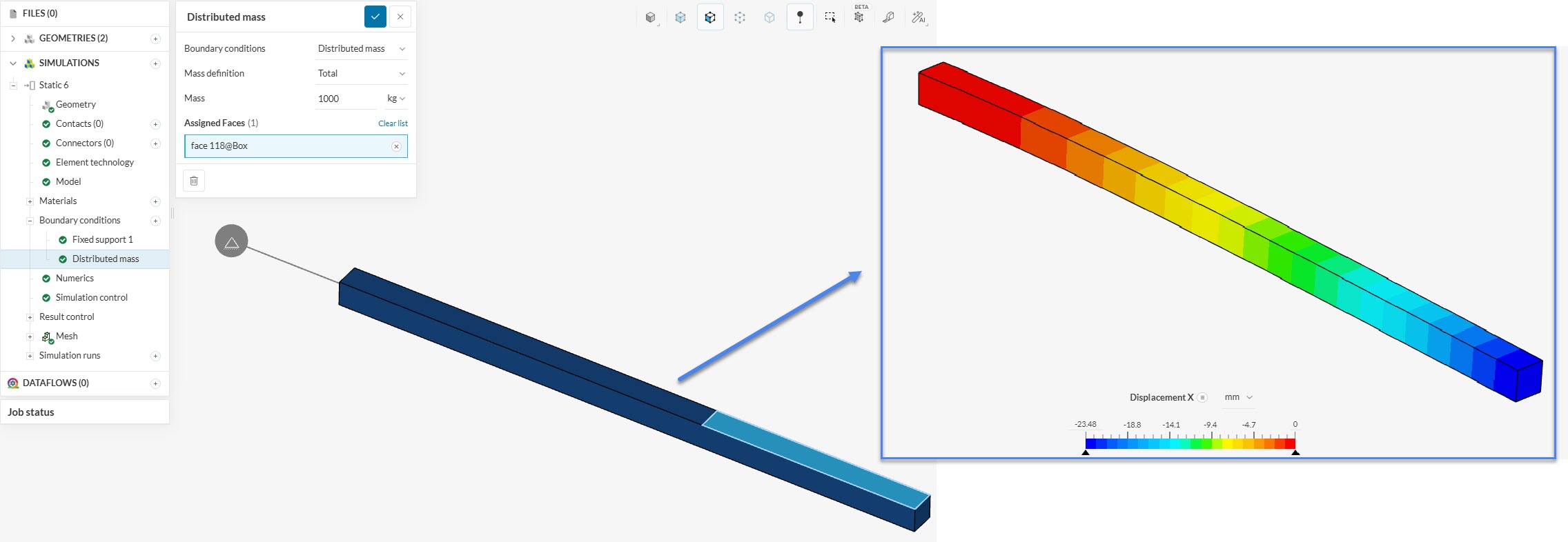
Taking into consideration the beam presented in Figure 2 with a total distributed mass of 1000 kg, the following displacement (deflection) is obtained in the x-direction:
Last updated: February 12th, 2026
We appreciate and value your feedback.
Sign up for SimScale
and start simulating now