This article explains the SimScale CAD associativity capabilities using NS_ tags for parts and surfaces, allowing the creation of simulation templates. Simulation templates allow the user to exchange geometries within one simulation while maintaining as many setup assignments as possible.
Overview
To compare different design variants, the same simulation has to be set up for different geometries. Therefore it can be useful to use a simulation template, with automatic assignments of boundary conditions. To achieve this the user can tag the name of parts and faces starting with ‘NS_’. The name tag will be detected and the parts and faces will be assigned by SimScale according to the simulation template.
How is CAD Associativity different to NS_ tags ?
CAD associativity allows the exchange of modified versions of the original CAD file, as long as the assigned faces and parts are still existing. Whilst NS_ Tags allow for the exchange of any CAD file, as long as the user-defined NS_ tags are identical.
SimScale allows for CAD associativity using Onshape or the SimScale Solid Works proven workflow.
NS_ Tags
By beginning the name of a surface or a part of the CAD model in your CAD Software with ‘NS_’, SimScale will check the CAD File on upload and create saved selections according to the tagged surfaces, and parts. This allows the user to assign the saved selections to the following inputs:
- Contacts
- Materials
- Boundary Conditions
- Mesh Refinements (Local element Refinement)
- Advanced Concepts
- Result Control Items
When exchanging the CAD file in a project SimScale will maintain the assignment of a saved selection. This feature enables the user to quickly exchange CAD files while maintaining the simulation setup, thereby allowing to quickly simulate different designs using the same simulation template.
Naming consistency
For the correct working of the automatic saved selection assignment, the tag has to start with ‘NS_’ and the exact name has to be assigned to a face.
You can find a short video demonstrating the usage and setup of NS_ Tags here:
Simulation Templates Example
In this example, we will create a template for an IGBT Cooler using NS_ Tags. We will then use the template in order to simulate a different variant of the IGBT Cooler. You can view the final project here:
NS_ CAD Tagging
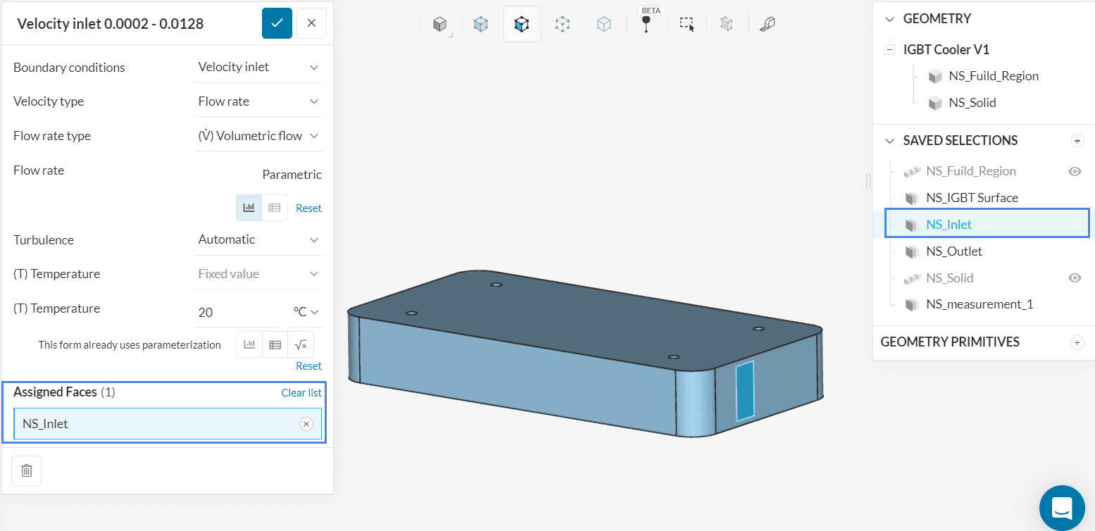
As a first step, we define the boundary conditions and materials for the simulation and tag the corresponding parts and faces. In addition, we also define a measurement surface, on which the temperature is evaluated in order to compare different designs. The figure below shows the setup for the simulation template:
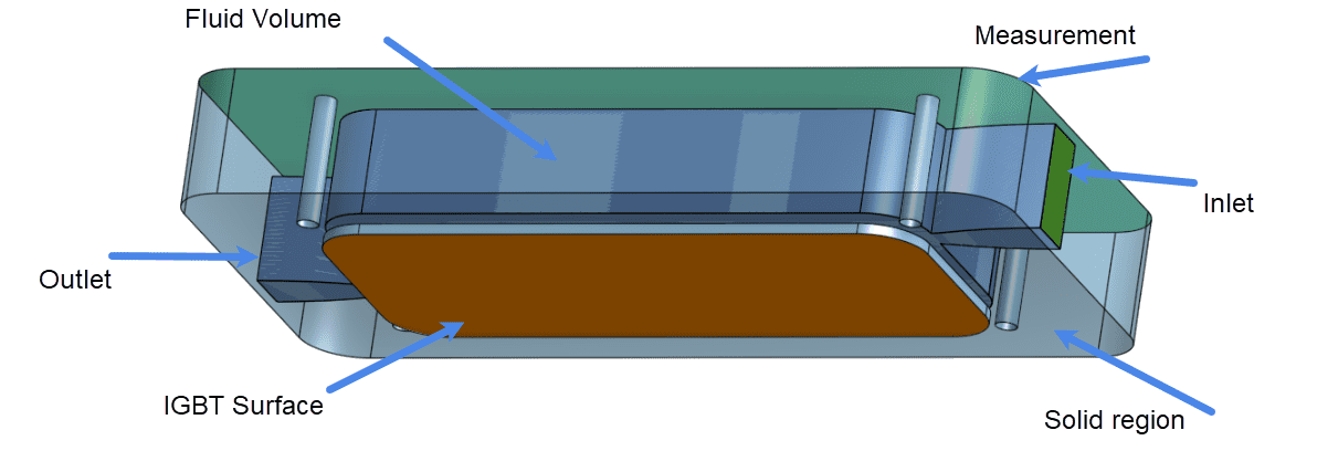
Parts
- Fluid Region: Water
- Solid Material: Copper
Faces
- Fluid Inlet: Volumetric flow inlet
- Fluid Outlet: Pressure outlet
- IGBT Surface: Constant temperature thermal wall
- Measurement surface
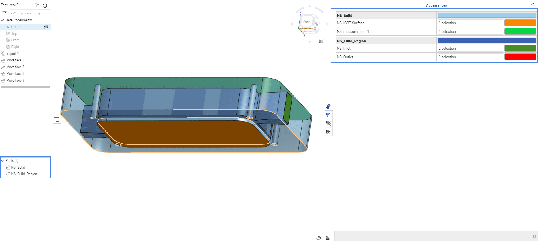
In this example, Onshape is used to rename the parts and faces. However, any CAD software can be used for renaming. The figure below shows the tagged faces and parts in Onshape.
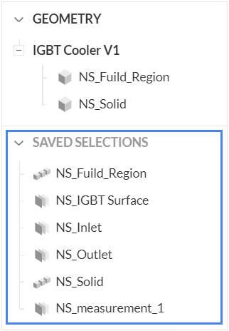
After CAD import to the SimScale platform, SimScale checks the CAD file and creates saved selections for the tagged parts and faces. The created saved selections can be seen below.
Setting up the Simulation Template
For the IGBT Cooler, a conjugate heat transfer analysis is necessary to simulate the heat transfer from the solid material to the fluid. This example focuses on the setup which is specific to the NS_ Tags. A more detailed tutorial on how to set up a Conjugate Heat Transfer Analysis can be found here:
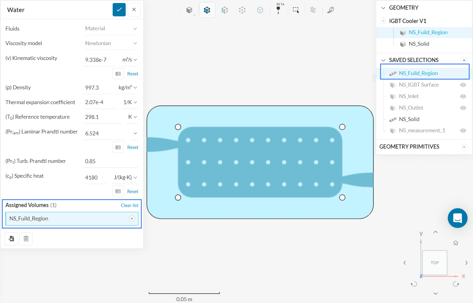
Material Assignment
First, we would like the simulation template to set up the material of the solid and the fluid region based on the tags. Therefore the saved selection are selected when assigning the volumes to the material.
Boundary Conditions
The same is done for the boundary conditions: here the velocity inlet, pressure outlet, and thermal wall boundaries are assigned to saved selections.
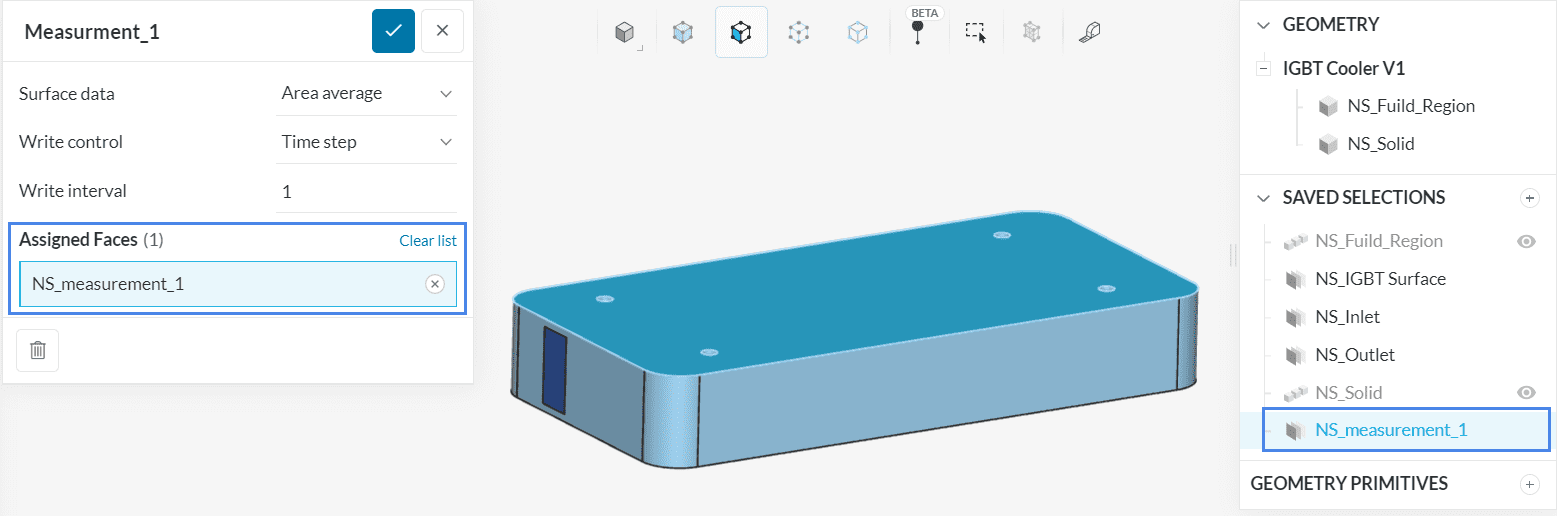
Result Control Item
Lastly, we will assign area average result control items to the outlet in order to obtain the pressure drop and the outlet temperature, as well as a measurement surface to obtain the temperature on the top of the IGBT. Here also saved selections are assigned.
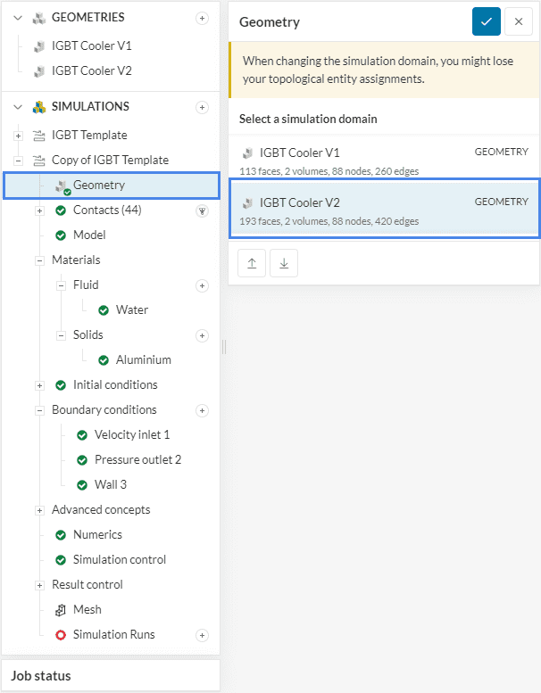
Using the Template and Maintaining Assignments
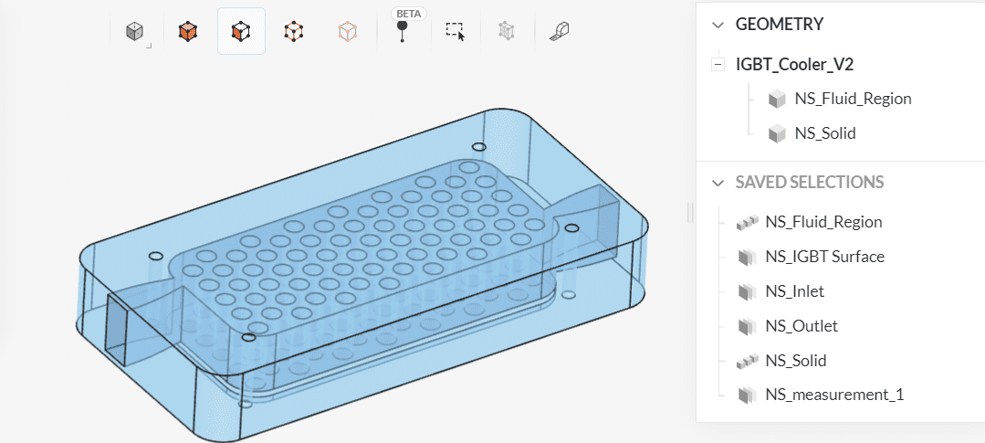
As the template is now set up, the new design of the IGBT cooler is uploaded. For the new design, the same tags have been set. The Figure below shows the new design with the saved selections created.
In this example, we will duplicate the template simulation within the same project. Another option would be to copy the entire project. This would ensure keeping a clean backup of the simulation template.
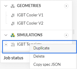
After duplicating the simulation template the geometry can be replaced. SimScale now detects the saved selections and replaces them accordingly. Without making any further changes to the simulation setup the new geometry can now be simulated.
After the successful run, we can compare the new design within the SimScale compare mode. We notice that the velocity distribution for the new model is more even compared to the template.
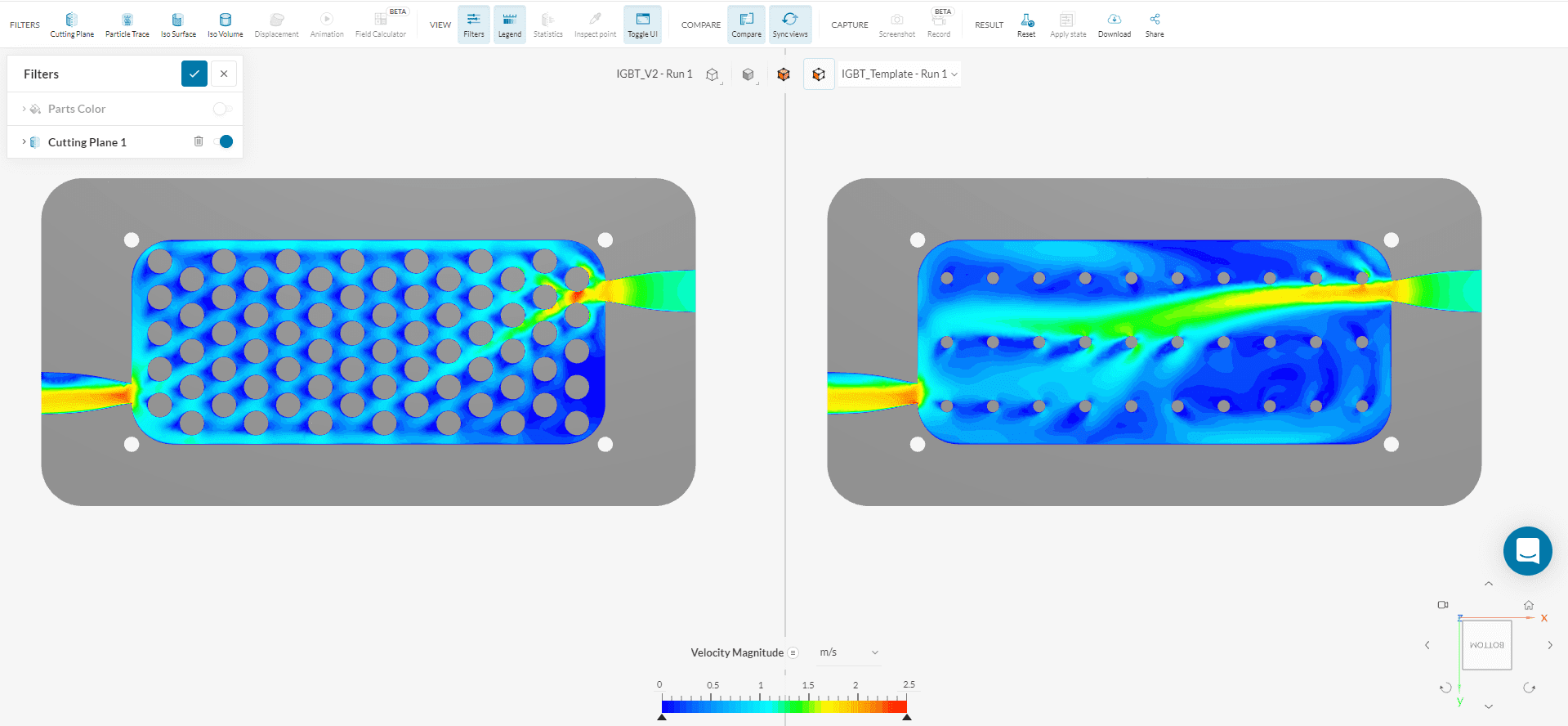
Comparing Simulations
Find out more about the SimScale Compare feature here.
Did you know?
Although the example from this article involves a CFD simulation, simulation templates also works for FEA analysis types.
Note
If none of the above suggestions solved your problem, then please post the issue on our forum or contact us.


