This article goes through CAD associativity capabilities using Onshape. This workflow allows the user to change geometries in a simulation tree while maintaining as many assignments as possible.
Overview
In a given simulation project, the user is often interested in testing multiple geometries that are similar between themselves. Having to re-assign faces and volumes to the simulation setup whenever changing a geometry can take some time, depending on the complexity of the CAD model.
To make the simulation setup process smooth, Onshape users can leverage the Onshape Connector App and maintain the assignments when switching geometries. The next section will go through a step-by-step example.
Example
To showcase the CAD associativity capabilities, the geometry from the Thermal Comfort in a Meeting Room tutorial will be used.
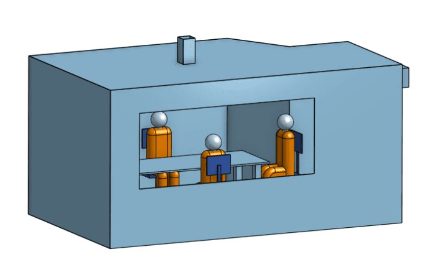
The initial geometry contains only the solid parts and no flow region. In CFD studies, to use CAD associativity efficiently, it is important to generate the fluid domain on Onshape before importing the CAD model to SimScale.
Generating a Flow Region on Onshape
There are many ways to create a flow region on Onshape, however, the easiest way usually involves the extrusion of a raw flow region followed by a Boolean subtract operation.
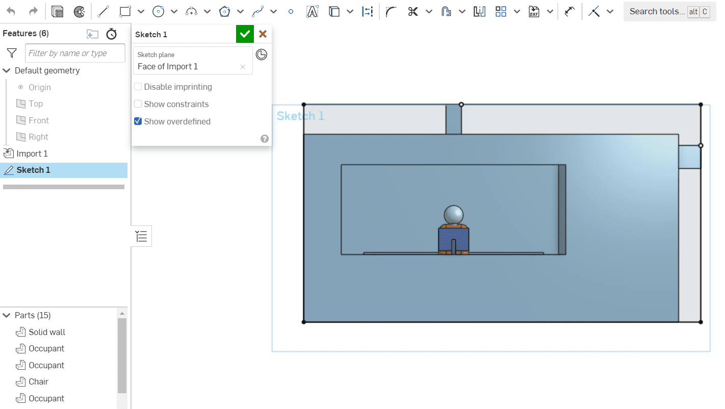
As an example, initially, we are going to use one of the outer faces of the room as a base for the sketch. A rectangle is created, perfectly enveloping the room:
After sketching the rectangle, an extrude operation is the next step. Here, the intention is to create a simple parallelepiped that envelops the solids completely.

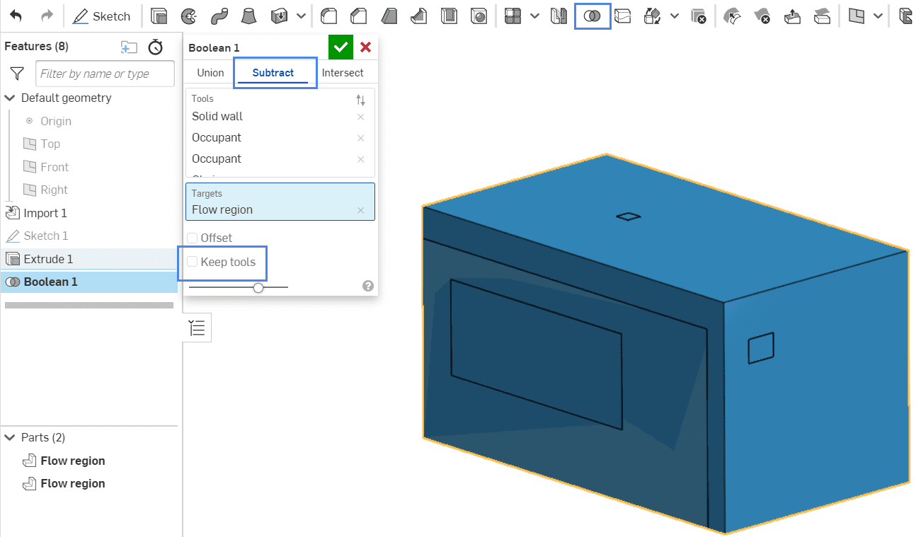
The new part that is generated in this process will represent the flow region after the next step. With a Boolean subtract operation, you can use the solid parts (Tools) to remove material from the newly created volume (the Target):
Finally, a ‘Delete body’ operation ensures that only the flow region of interest remains.
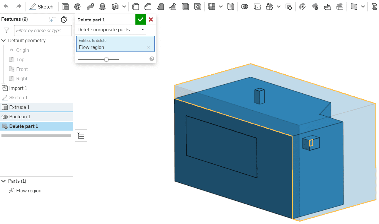
This is going to be the first version of the CAD model to simulate.
The objective is to make adjustments to the initial version of the CAD model and maintain as many assignments as possible in the simulation tree.
Changing the CAD Model and Importing a New Version
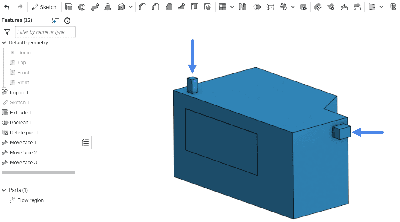
After running a simulation with the initial CAD model, the user might be interested in making small adjustments to the geometry and running more simulations. As a demonstration, let’s say that a ‘Move face’ command is used to reposition the inlet and outlet:
When importing the new CAD model to SimScale via Onshape, you can take advantage of the CAD associativity capabilities.
Maintaining Assignments in the Simulation Setup
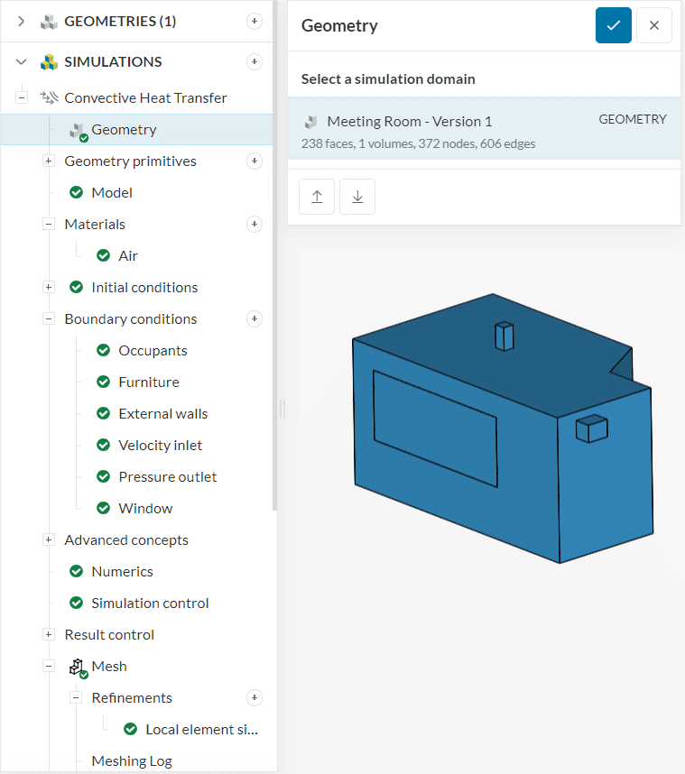
To keep the setup assignments, the best way to proceed is to duplicate the initial simulation tree and assign the new geometry in the Geometry tab:
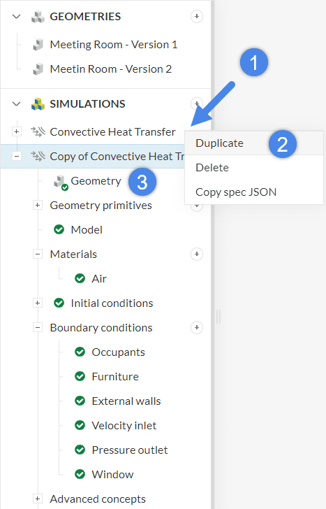
- First, By right-clicking on the first simulation tree, a window appears with options
- Select ‘Duplicate’ to duplicate all settings from the first simulation tree
- Select ‘Geometry’ in the new simulation tree, and assign the updated geometry
After the user selects the new geometry, all assignments are kept:
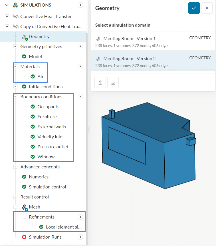
Since SimScale keeps all assignments in this example, the user can directly proceed to the meshing and simulation operations.
Depending on the CAD changes performed, some assignments may be lost, however, SimScale will maintain as many as possible.
Did you know?
Although the example from this article involves a CFD simulation, associativity also works for FEA analysis types.


