A variety of quick selection tools are available within SimScale. This article aims to provide a brief overview of the various selection tools and their functionalities.
Selection Basics
In order to choose the right selection tools, here are a few basics every SimScale user should know:
Choose the Selection Mode
Centered at the top of the viewer, the viewer toolbar allows you to pick a selection mode. Usually, you either want to select whole solids or only specific faces.
Depending on the context, either faces or whole solids need to be selected or assigned. In most cases only one assignment mode is possible. If this is the case, the workbench will automatically select the correct selection/assignment mode for you. In case a mix of assignments is possible, it’s common that you’d like to assign all faces of a specific solid part. If this is the case, select not each individual face, but simply assign the whole solid part instead.
Note
Mesh upload is mandatory if Edge selection or Node selection needs to be used.
Selection Modes
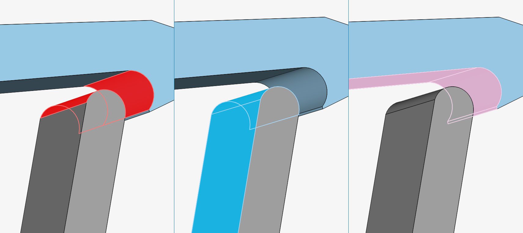
You might have noticed that a selection is sometimes shown in red, other times in blue, or even pink. The color used for highlighting a selection in the viewer depends on the current selection or assignment context:
- Standard selection mode: red
- Assignment mode (or contact master assignment): blue
- Contact slave assignment mode: pink
Now that we have the basics covered, find below an introduction of the main selection tools for making a quick and easy selection via the viewer:
1. Mouse and Keyboard Controls
Besides selection tools, several functions are available via mouse and keyboard hotkeys. The table below shows an overview:
| Effect | Command (Windows) | Command (Mac) |
| Select | Simple left-click | Simple left-click |
| Rotate | Drag with the left mouse button | Drag with the left mouse button |
| Axis stable rotation (rotation around the axis normal) | Drag with the left mouse button and hold x, y, or z key | Drag with the left mouse button and hold x, y, or z key |
| Pan | Ctrl + left-click Drag with the middle mouse button | Control + left-click Drag with the middle mouse button |
| Open drop-down menu with options | Simple right mouse click | Simple right mouse click |
| Zoom in/out | Alt + left-click Drag with the right mouse button Scroll wheel up/down | Option + left-click Drag with the right mouse button Scroll wheel up/down |
| Box selection tool shortcut | b | b |
| Hide selection | h | h |
| Save/confirm changes | Enter | Enter |
| Escape/discard changes | Esc | Esc |
| Revert camera position and zoom level to default values | a | a |
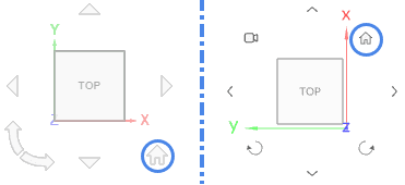
How axis stable rotation works?
2. Box Selection Tool
This tool is commonly used in CAD software and also made its way into SimScale.
Once Box selection is activated in the viewer, the user has two options to select the entities:
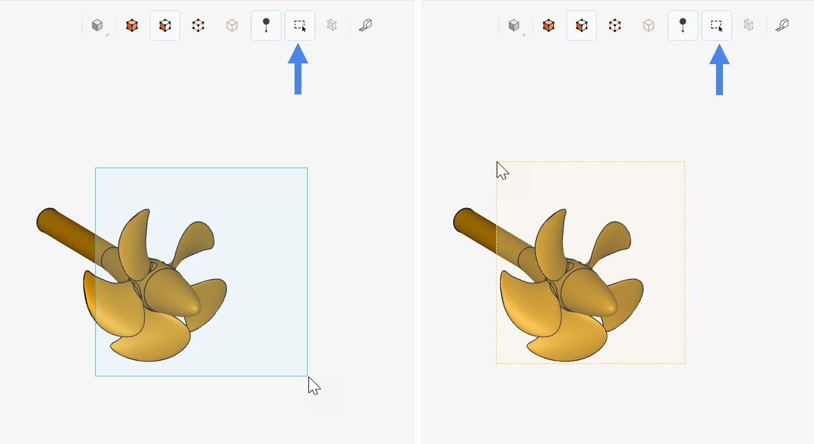
- Clicking and dragging the cursor from left to right: entities fully contained within the box are selected;
- Clicking and dragging the cursor from right to left: entities that are intersected by the box are selected.
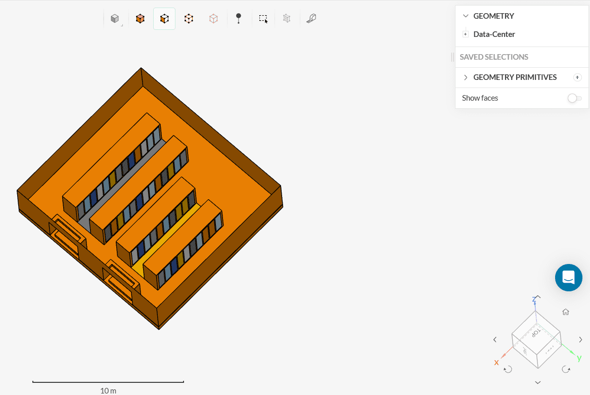
This type of selection comes in handy for geometries with a big number of faces. As an example, let’s have a look at the data center geometry below.
It’s possible to quickly select all faces from a server line in one click:
- Make sure that the Face selection and the box selection icons are enabled;
- Create a box containing the entire server line. Note that, in this picture, the box was drawn from left to right.
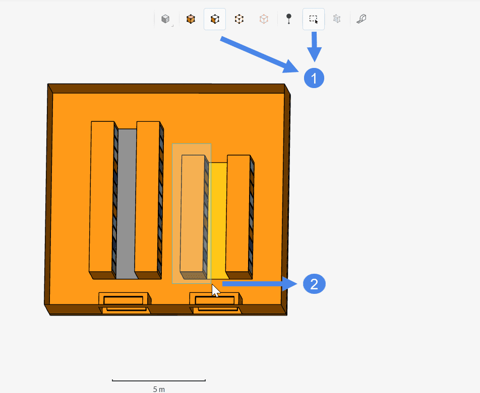
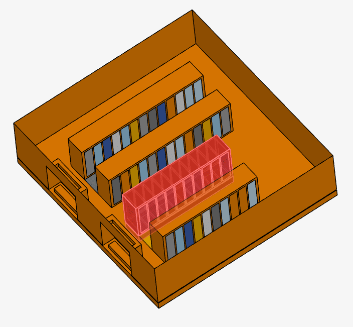
As a result, we select a total of 109 faces.
3. Invert Selection Tool
In some cases, we would like to select the vast majority of faces in a model. Instead of selecting all of them one by one, we can simply select the ones we don’t want and then invert the selection.
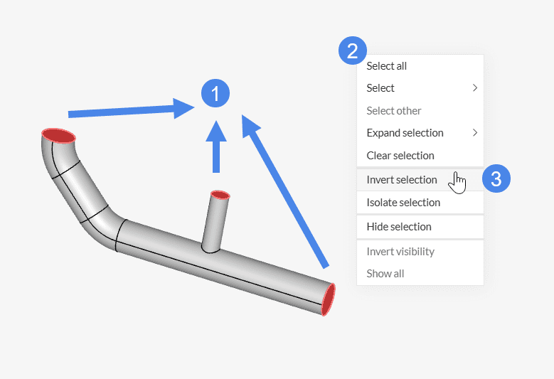
Let’s take the following example: we are interested in selecting all walls from a pipe geometry.
The first step is to select the unwanted faces. In this case, 2 inlets and 1 outlet. Afterward, simply right-click in the viewer. In the window that opens, select Invert selection:
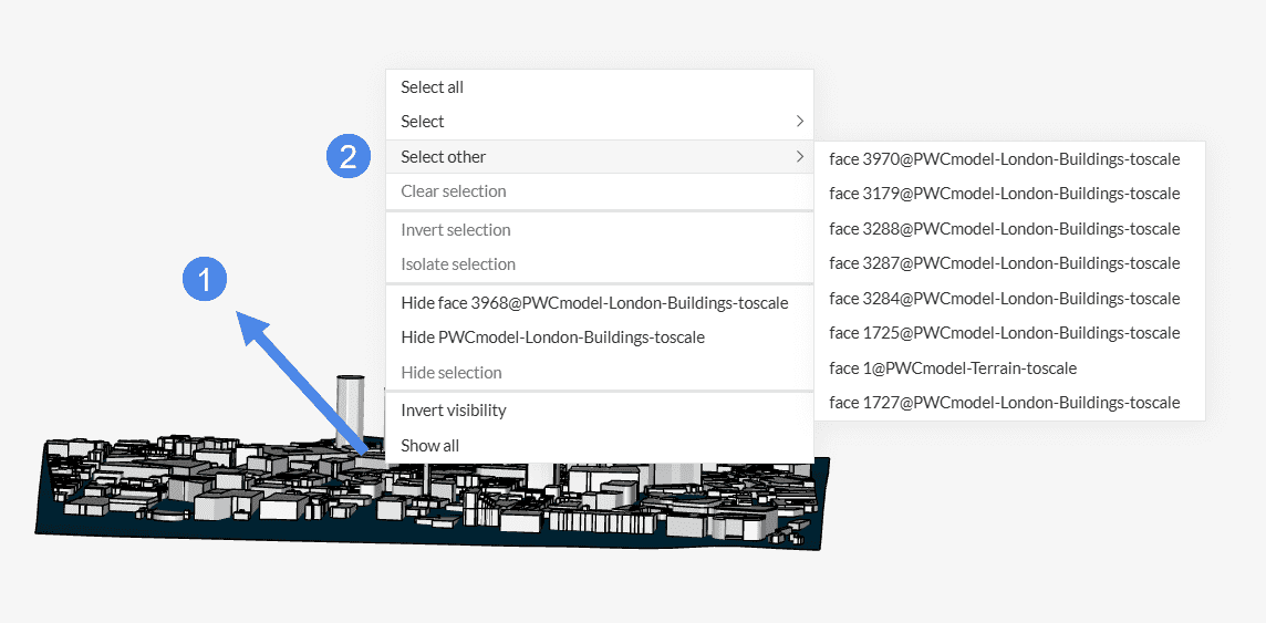
4. Select Other
A handy tool for selecting a face hidden behind another face is the “Select other” feature. Now, simply right-click on a specific face in the viewer and when clicking on ‘Select other’ a list of faces behind the current location will be offered for selection.
5. Expand Selection
SimScale offers options to extend the selection of faces based on the current selection, both in the Workbench and CAD mode environments. Users can extend their selection based on tangent faces, faces with the same area, and fillets with the same radius – these options are explored below.
Tangent Faces
The image below shows the steps to expand the selection based on Tangent faces:
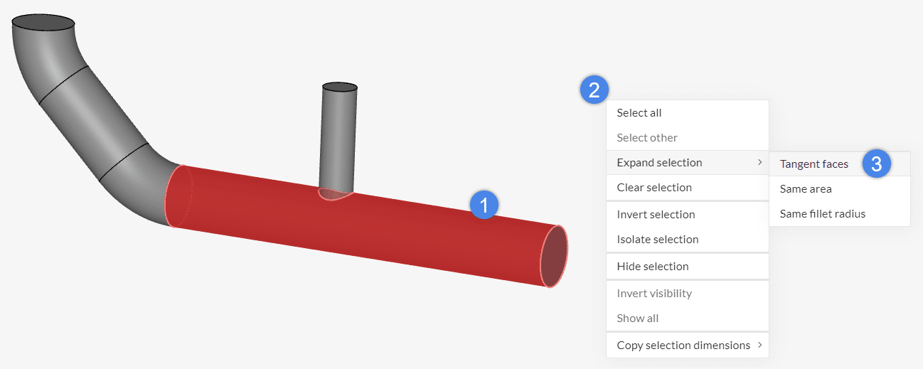
- Select at least one face of interest
- Now, right-click on the viewer and choose ‘Expand selection’ from the list
- Select ‘Tangent faces’
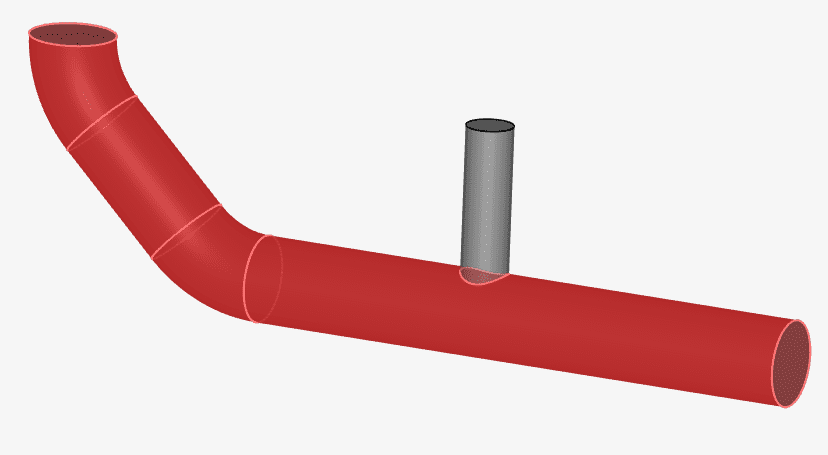
At this point, the platform selects all faces tangent to the initial selection.
Same Area
Another possibility is to expand the current selection to other faces with the same area.
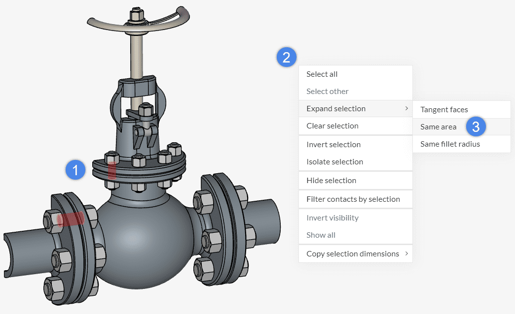
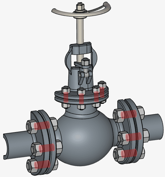
As a result, all faces with the same area of the initial selection are added to the selection.
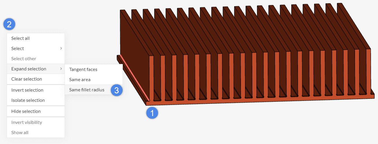
Same Fillet Radius
Oftentimes CAD models contain several small fillets which add little accuracy to the solution, but make meshing less optimized. The Same fillet radius selection is helpful in such cases, especially in the CAD mode environment when combined with the delete face command.
In the heat sink model below, the CAD model contains dozens of small fillets. By selecting one of them, we can select all fillets with the same radius:
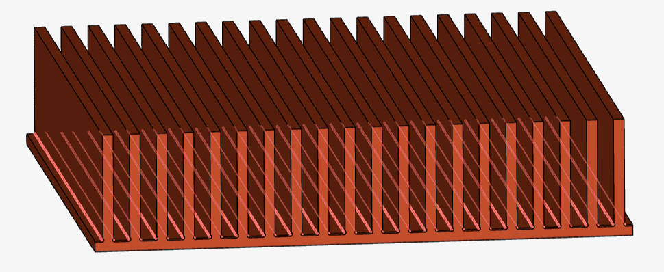
As a result, all fillets with the same radius are added to the selection.
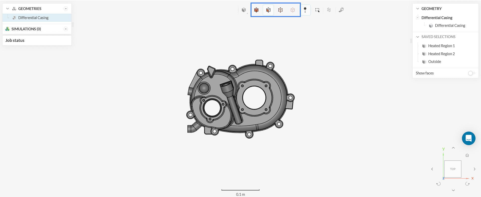
6. Saved Selections
Saved Selections are groups of faces that the user wants quick access to. It’s useful to create sets for groups of faces that will be used multiple times in the setup.
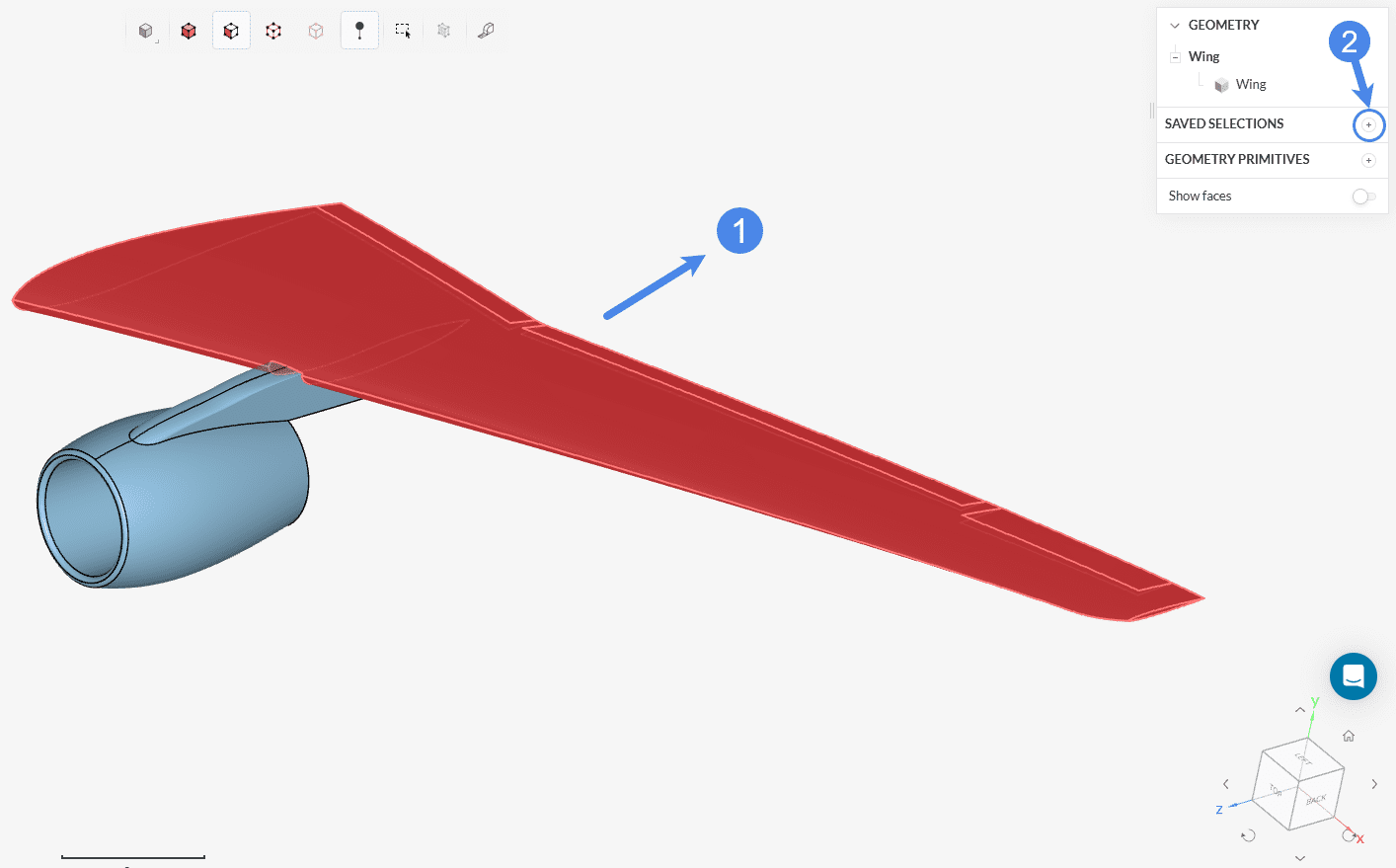
To create a saved selection, please follow these steps:
- Select the faces that will be part of the saved selection;
- In the right-hand side panel, click on the ‘+’ button next to Saved Selections;
- Give the saved selection an appropriate name;
- You can access the created sets in the right-hand side panel.
7. Copy or Duplicate
You can use copy/duplicate features to clone a project, a simulation setup, a geometry primitive, a material, a boundary condition, or a result control item. It is usually practical to create an identical clone and edit it, instead of setting it from scratch.
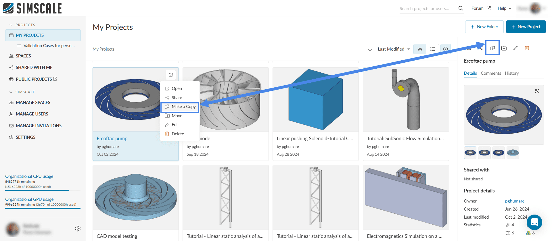
You can copy an existing project by pressing the copy icon as in the image below. This can be done also from inside the Workbench, look for the copy icon in Figure 1.
You can duplicate an existing simulation setup as well. This is practical if you would like to test the existing simulation setup with some minor changes; or if you would like to use the same setup on a new CAD model. The .gif below shows how to duplicate the setup and change the CAD model:
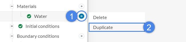
You can duplicate an existing setting by clicking on the ![]() icon next to it. This is possible for the following items in the simulation tree:
icon next to it. This is possible for the following items in the simulation tree:
- Geometry primitives
- Materials
- Subdomains under the initial conditions
- Boundary conditions
- Advanced concepts
- Result control items
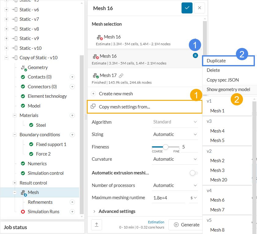
You can duplicate the mesh settings on an existing CAD model. Alternatively, you can copy the mesh settings from another CAD model, as shown below:
8. Fit To Screen
In the right bottom corner of the Workbench or the post-processing environment, users can find the orientation cube that is helpful in adjusting the view angle. Additionally, the “home” icon is useful when trying to fit the existing model to the screen. Clicking the icon will adjust and zoom-fit the model appropriately within the screen.
With these simple selection tools, users can save time during the setup of their simulations.
Note
If none of the above suggestions solved your problem, then please post the issue on our forum or contact us.
9. Measurement Tool
The measurement tool comes in handy when checking different dimensions of the CAD models. It can be useful to double-check the scale of your CAD with a specific reference, access dimension values easily, measure the distance between two entities, like nodes, edges, faces, and much more.
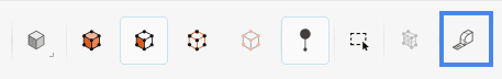
You can find this option in the toolbar at the top of the viewer in Workbench or CAD mode.
With this feature, you can work with two different approaches:
- Get the dimension value of a specific entity (volume, area, length, center of mass, distance between two vertices, etc.)
- Measure the distance between two entities
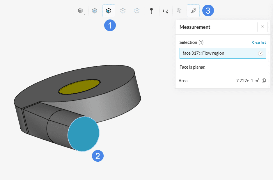
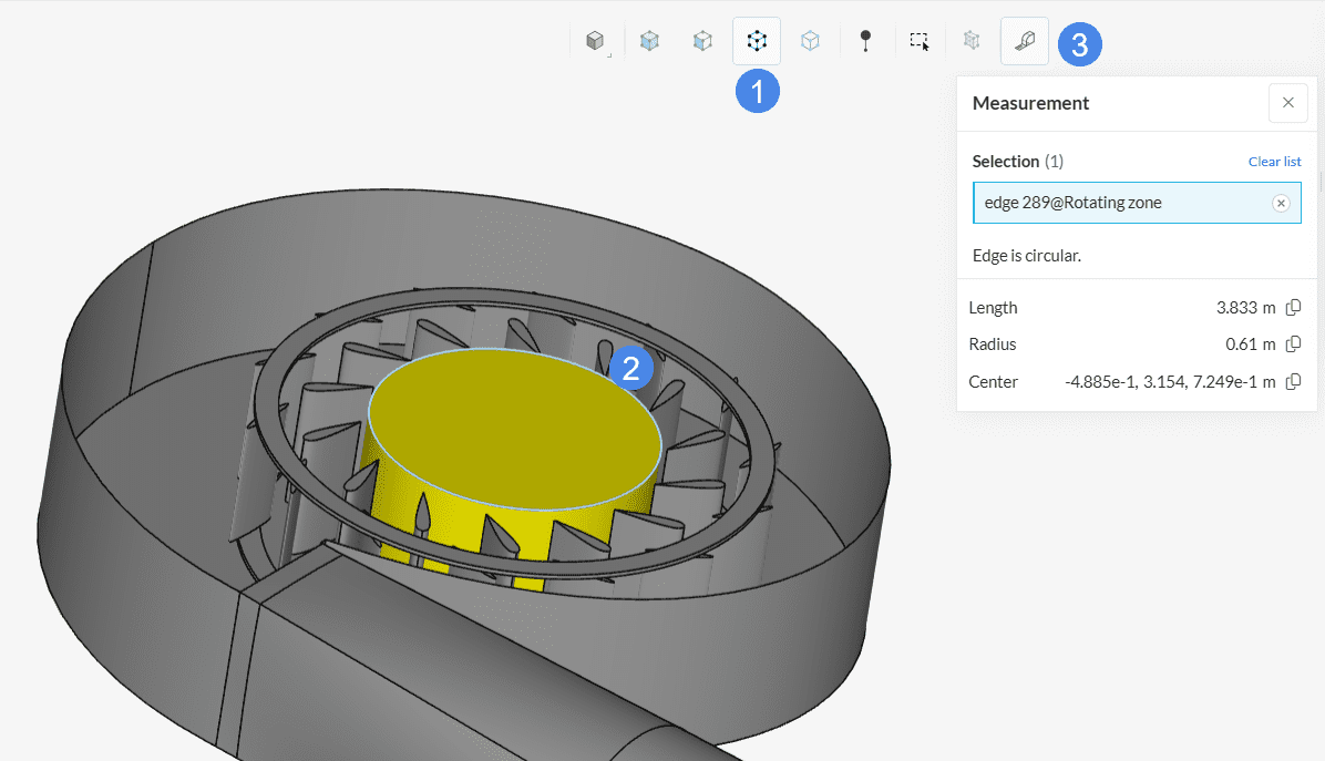
Dimension Value of a Specific Entity
If the goal is to know a specific dimension of an entity, select the entity (volume, face, or edge) and click on the ‘Measurement tool’ icon. The platform will open a new window with the dimension values.
It is possible to obtain the radius or center points of a region by selecting its edge.
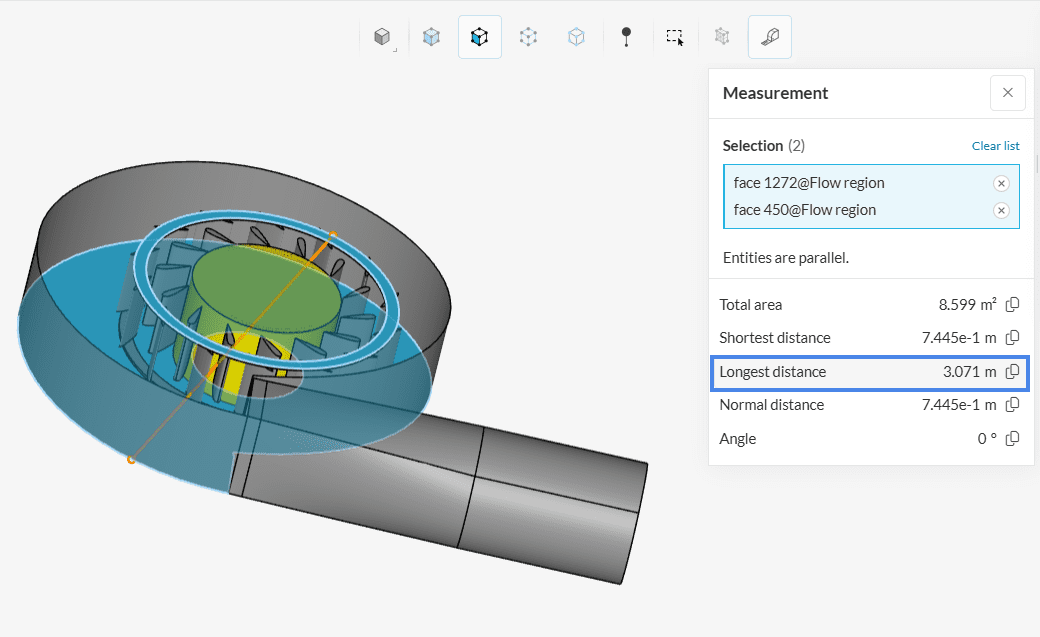
Measuring the Distance Between Two Entities
Using the measurement tool you can also check the distance between two entities. To work with this option, instead of selecting one entity you must select two entities and the tool will calculate the shortest, longest, and normal distance between the entities and the angle.
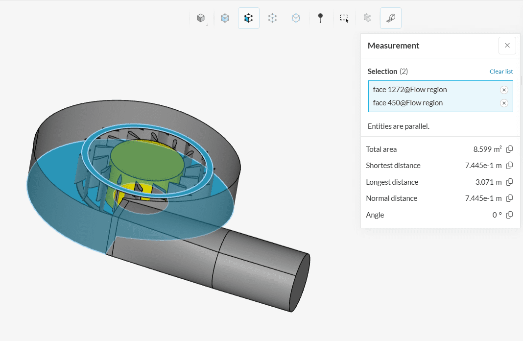
To visually identify how the distances between the selected entities were calculated, simply place the mouse over one of the calculated values in the panel and you will see a line connecting the points: