This knowledge base article will guide you on how to check mesh quality and how to improve it.
Approach
A high-quality mesh is one of the most critical factors that must be considered to ensure simulation accuracy, and this is why it is very important to check and improve your mesh quality. In this article, we will use the Standard mesher as an example.
Please visit this tutorial to learn how to use the standard mesher within SimScale.
The following topics are discussed:
- Checking the Meshing Log to have a quantitative idea about the overall mesh quality.
- Visually inspecting the mesh.
- Using the Mesh Quality feature to locate bad elements.
- Improving mesh quality
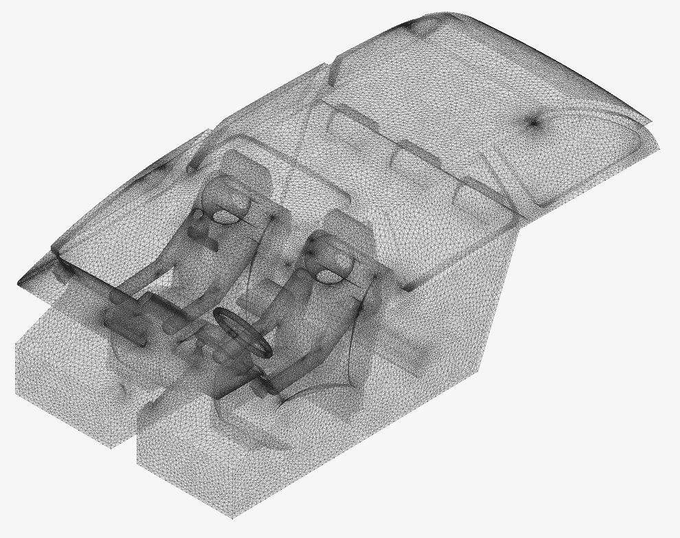
The picture above is the initial mesh that will be used as an example.
1. Meshing Log
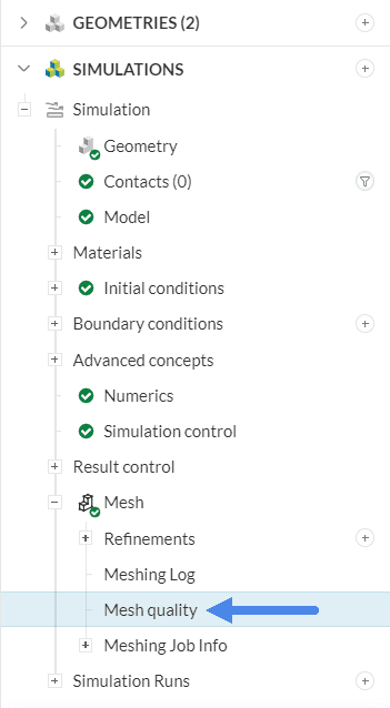
To begin, create the mesh for your simulation. Once the mesh generation is complete, you can review the mesh’s quality by accessing the Meshing Log, which is located under the Mesh settings in the simulation tree.
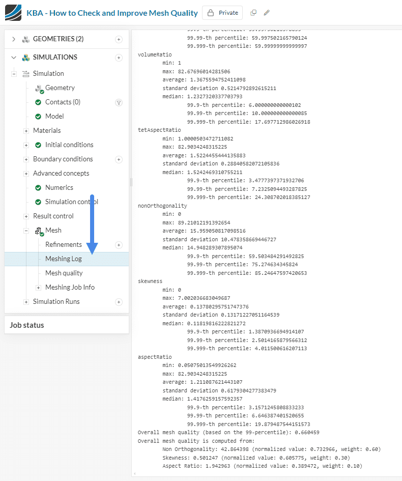
The Meshing Log provides statistical data on the generated mesh, referred to as mesh metrics. These metrics vary depending on the type of mesh used. It is crucial to monitor these values, as they significantly influence the accuracy and convergence of your simulation results.
As a best practice, consider the following reference values to assess and improve your mesh quality:
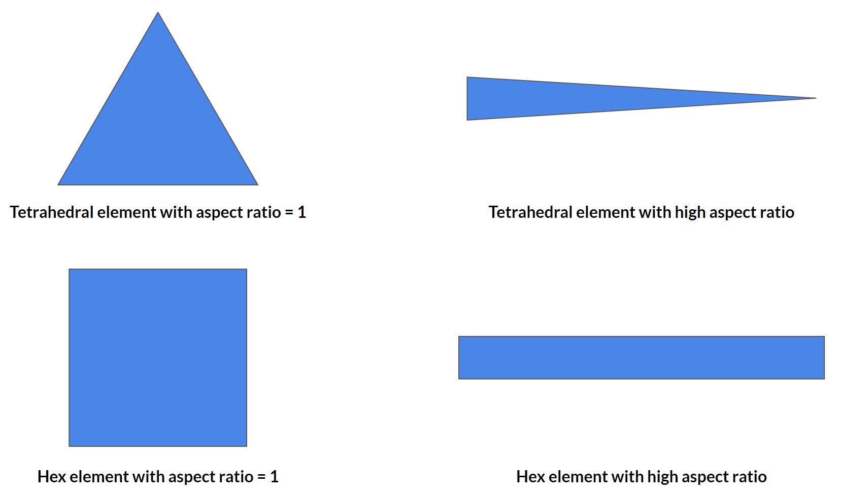
- tetAspectRatio: \(\ll \) 100
- Non-orthogonality: \(\ll \) 88
- tetEdgeRatio: \(\ll \) 100
- VolumeRatio: \(\ll \) 100
Different metrics for FEA/CFD
Whereas keeping all of these values controlled is always a good approach to achieving simulation convergence, there are some which are more relevant to FEA/CFD analysis. As a general rule, CFD simulations with a Non-orthogonality higher than 88 are very likely to fail. For FEA the relevant metrics are Skewness (< 10) and Aspect/TetAspect Ratio (< 30/16).
For more information, take a look at the corresponding section from the general documentation on Mesh Quality.
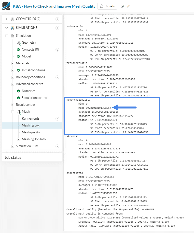
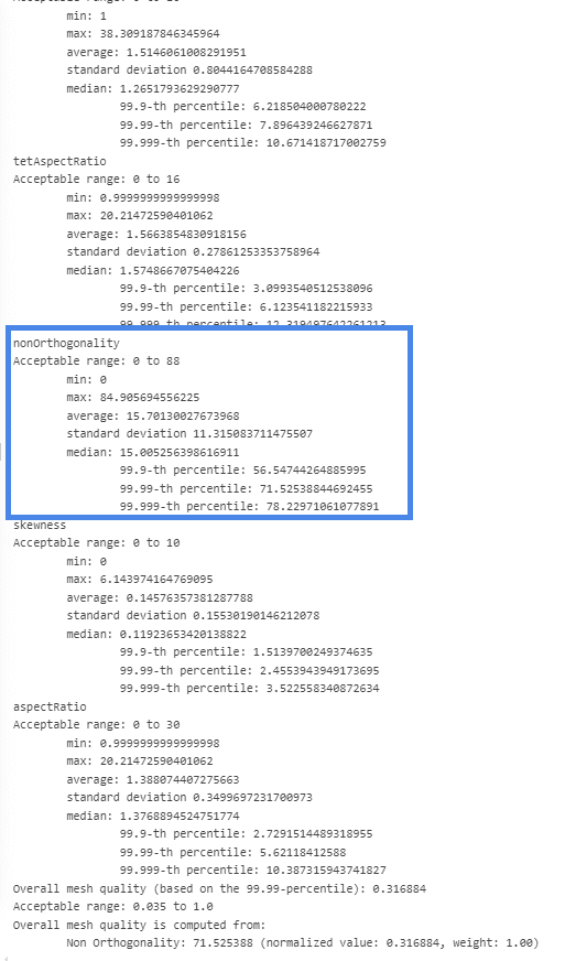
The picture below shows that the mesh for our Car Interior Model is lacking in quality, especially when looking at its non-orthogonality which is above 89:
Now, we have learned how to identify a bad quality mesh, but what is the cause and where are these bad quality elements located? Let’s find out.
2. Visual Inspection of the Mesh
The primary objective of visually inspecting a mesh is to identify potential issues, particularly in areas where:
- Boundary layers exhibit irregular behavior (e.g., collapsing)
- The model’s resolution appears too coarse
- There is a noticeable concentration of cell elements
For instance, during this analysis, we’ll focus on identifying regions with high cell concentrations, as this is one of the most common issues that can be detected through visual inspection.
Let’s take the spot highlighted in the figure below as an example:
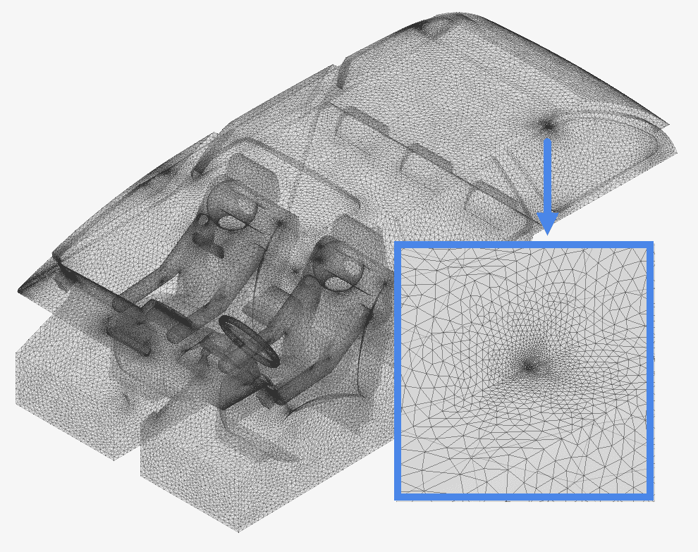
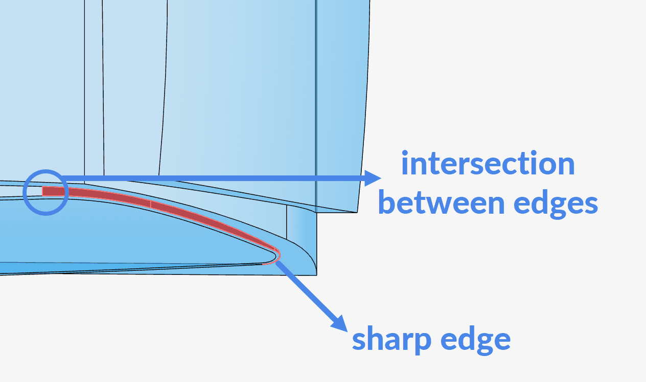
By looking at the mesh, it seems like some feature in the original CAD model is making elements near this point smaller in size. If we zoom in, we find out that there’s an edge intersection causing this to happen – and as an additional byproduct of our inspection we can also see a potentially problematic small face leading to a sharp edge!
Cells tend to concentrate in specific regions because the mesher attempts to capture the intricate features of the original CAD model. To achieve a smooth transition between small and large cells, the mesh becomes particularly fine near these areas.
Unwanted features in the CAD model
The preparation of a CAD model depends on its intended application – whether in architecture, 3D printing, manufacturing, or another field. Simulation is no exception. For effective simulation, the CAD model should be as streamlined as possible, minimizing unnecessary small faces and edges that can result in an excessively large mesh. Simplifying the model in this way ensures better performance and more accurate simulation results (form more information take a look at our CAD Preparation and Upload documentation).
This is interesting because, as will be discussed further, CAD cleaning is the most effective way of reaching a high quality mesh.
3. Mesh Quality Feature
Mesh quality is a SimScale feature, which visualizes the element quality. You will find this feature below the Meshing Log. In this example, we will focus on reducing the maximum value for our Non-orthogonality.
3.1 Results
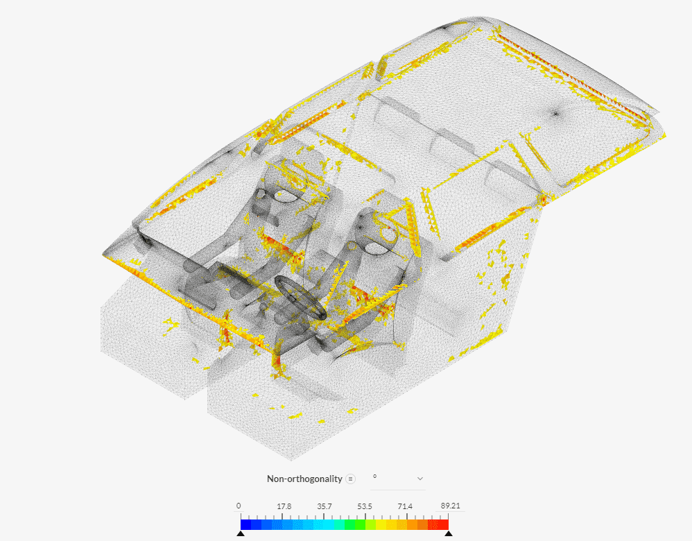
To visualize the Non-orthogonality, do the following:
- Click ‘Mesh quality’
- Apply ‘Non-orthogonality’ to the Coloring option under Parts Color.
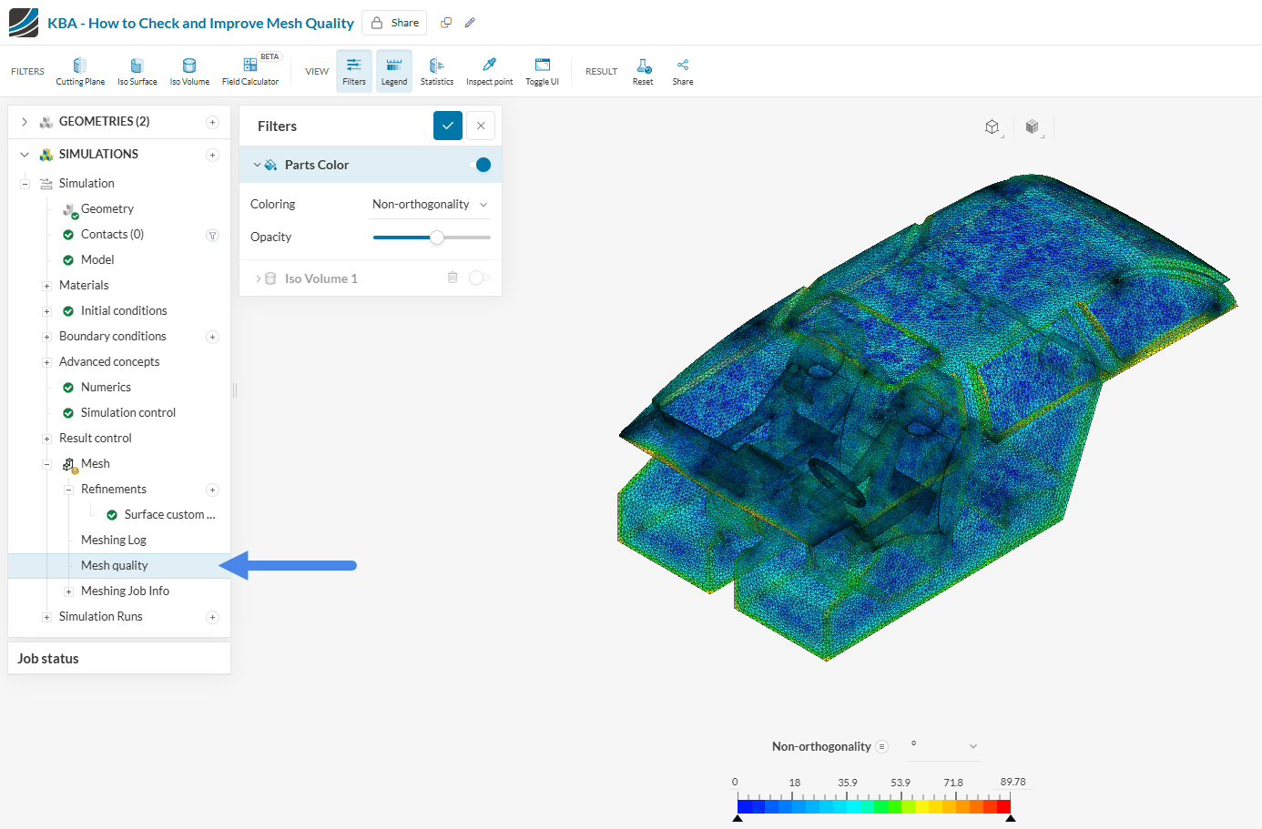
The non-orthogonality varies significantly across the domain, as indicated by the color gradient aligned with the legend. However, to effectively identify and address elements with poor quality, it’s best to isolate them. This can be achieved using Isovolumes.
3.2 Isovolumes
Isovolumes serves as a filter to isolate elements, whose non-orthogonality falls under a defined range. In this example, we will find mesh cells that have non-orthogonality between 80 and 89.99. The steps below explain how you can isolate these elements:
- Go to the Mesh quality viewer
- Click the ‘Iso Volume’ icon.
- Type the range of the Non-orthogonality you are interested in, which is 80 to 89.99 in this case. Keeping the non-orthogonality below 88 is usually enough for a first convergence of the model – especially if there are non-orthogonal correctors put in place.
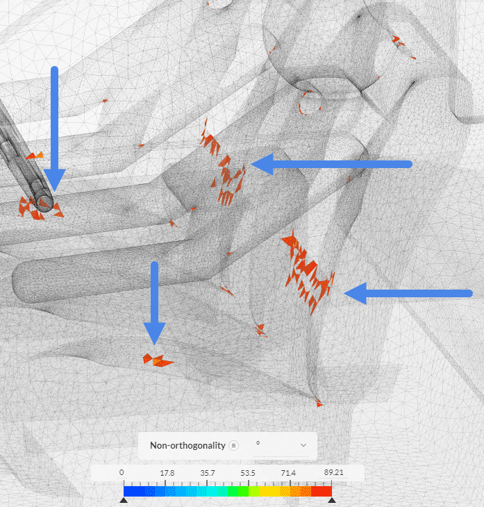
- Locate the highlighted elements on the screen.
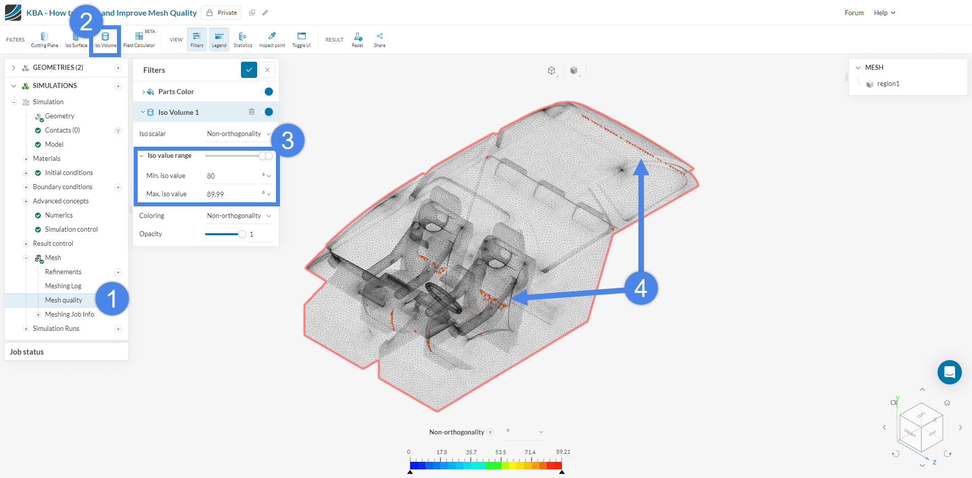
In the picture above, bad elements can be seen, but you can focus on the bad elements by zooming in.
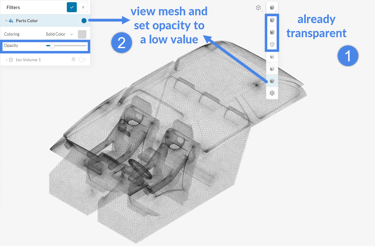
How to use transparency in the mesh quality viewer?
There are two ways to set your model to a lower opacity in the mesher:
- Select a render mode and set Opacity to a lower value under Parts Color.
Now that we’ve identified the locations of the problematic elements, it’s important to understand that these issues – as pointed earlier – often stem from CAD model imperfections, such as poorly defined surfaces, small gaps, or sharp corners. The most cost-effective solution is to address these issues through CAD cleaning.
However, if CAD cleaning isn’t an option, you can either refine the mesh across the entire domain or focus specifically on the areas with poor-quality elements. These two approaches will be our next steps.
4. Improve Mesh Quality
The meshing log might report a bad mesh quality. This is usually bad news but does not necessarily mean that the mesh is inconvenient to use. If there are only a few elements that have bad quality, and if those elements are not at the inlet or outlet boundaries, probably the simulation will still work all right.
There are two ways to improve the mesh quality:
- CAD cleaning: Modify the CAD model to prevent the generation of bad quality elements. As an example, remove the tiny gaps, remove the sharp angles, defeature, remove the small features.
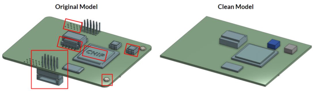
Figure 12: Common CAD cleaning measures on PCBs
- Mesh settings: Perform manual adjustments to prevent the generation of bad quality elements. For instance, adjust the global mesh settings and add manual refinements to control the cell size.
Mesh quality metrics are highly correlated to each other. In other words, if the Aspect ratio is bad, most probably the other quality metrics will be bad too. Therefore, it is important to aim for reducing the maximum AspectRatio quality metric.
Some useful tips to reduce the maximum Aspect ratio are listed below. Keep in mind that these measures won’t always work. The best workflow is to understand why the quality is bad and apply a corresponding measure accordingly:
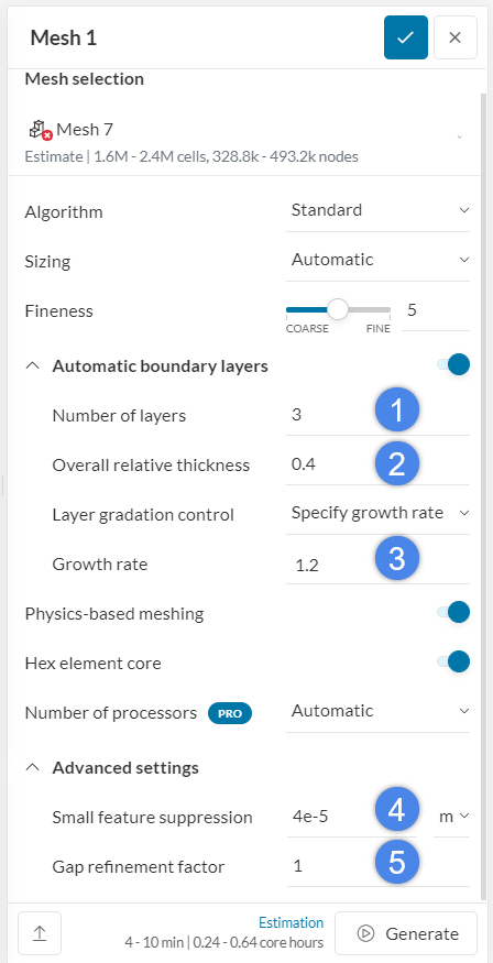
- Reduce the ‘Number of layers’: Use at least 1 layer. If you are aiming for the correct y+ range, ignore this measure.
- Increase the ‘Overall relative thickness’: Keep the range between 10-60%. If you are aiming for the correct y+ range, ignore this measure.
- Reduce the ‘Growth rate’: Keep the range between 1.1-1.5. If you are aiming for the correct y+ range, ignore this measure.
- Increase the ‘Small feature suppression’: This value will determine the smallest edge length in the mesh, as well as the smallest cell size. Keep in mind that if this value is too high, the mesher will fail.
- Increase the ‘Gap refinement factor’: Usually, 0.5 will improve the mesh quality significantly. Ideally, keep this value above 1. Keep in mind that increasing this value will increase the overall mesh size significantly if there is a considerable volume of gap region/s in your model.
6. Use ‘Local refinement’ and ‘Region refinement’ to locally control the maximum cell size. For example, if there is an edge with a size of 1 \(mm\) in the CAD model, assign 1 \(mm\) maximum edge length at this region.
7. If you are using manual mesh refinements, be conscious about the cell size assignment. Above all, sudden cell size changes to keep the VolumeRatio small.
Example 1: Trying to Refine the Elements Locally
Previously, we found some regions with bad element qualities (Figure 5 and Figure 6). You can always use SimScale’s automatic sizing feature to adjust the mesh size. Increasing the Fineness level will gradually increase the mesh size in the overall domain.
Another possibility is to refine the mesh in the problematic region with a Local element size.
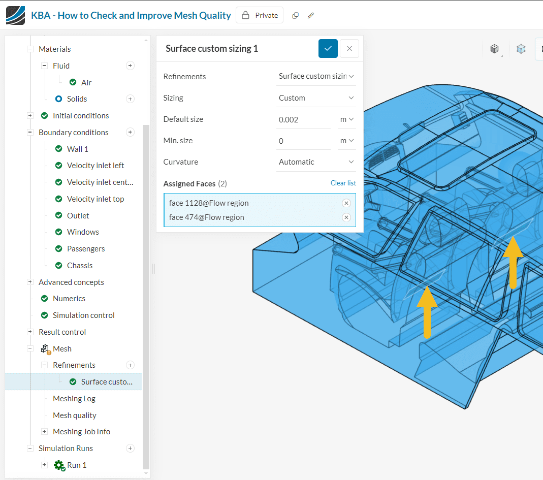
Figure 6 shows the problematic region where there is a sharp edge in contact with an irregular surface. This is a problem because when the thickness of this face becomes too small, sharp edge cells are generated in this region. We will try to apply a Local element size refinement to solve the issue. For that:
- Add a Surface custom sizing refinement.
- Select the faces where it will be applied.
- Assign a suitable cell size.
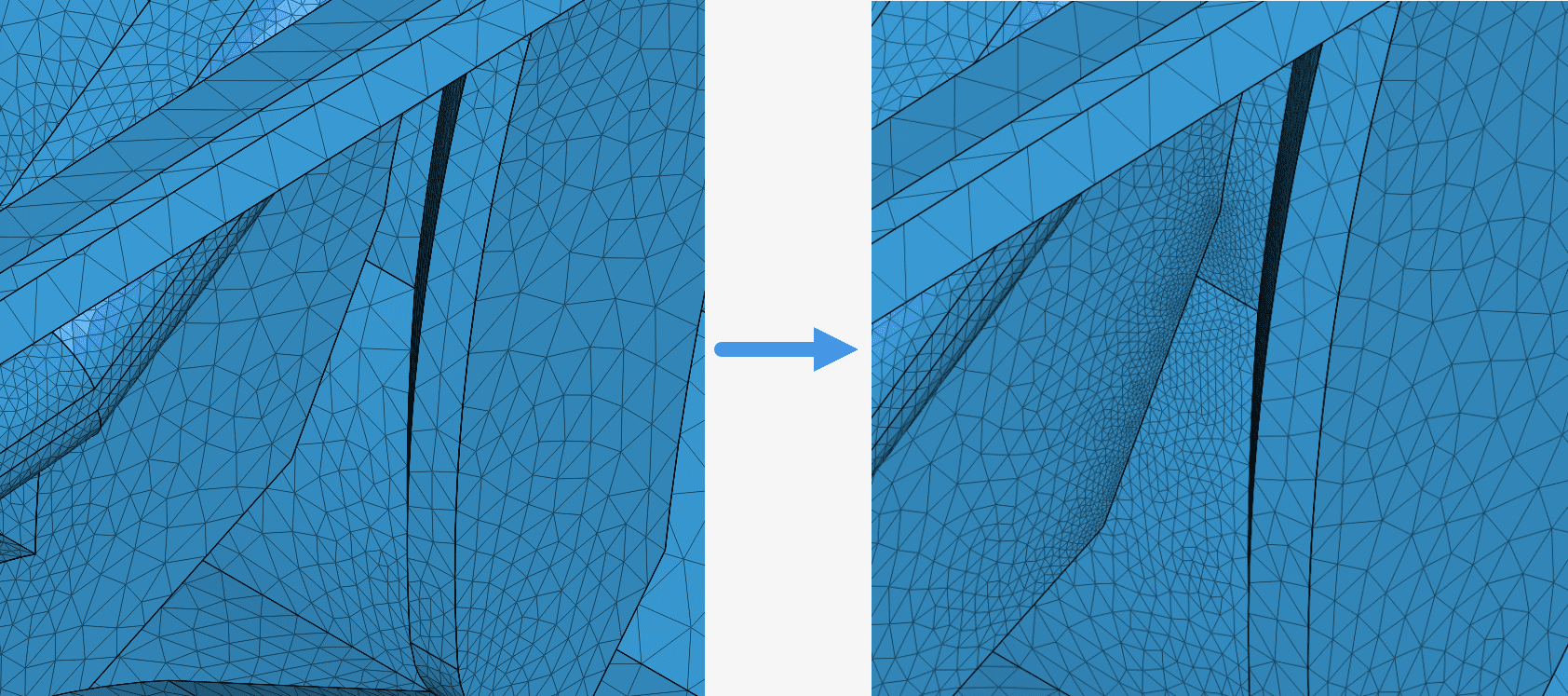
The difference between the two meshes is notable when looking at the region of interest, as presented in the picture below.
Example 2: Cleaning up the CAD
After regenerating the mesh, we will get a new mesh with new mesh quality statistics. In this particular case, the local refinement wasn’t enough to solve the issues with the mesh and made it much larger as a result. A better option then, seemed to be cleaning up the geometry altogether.
In our case, one option might be the following:
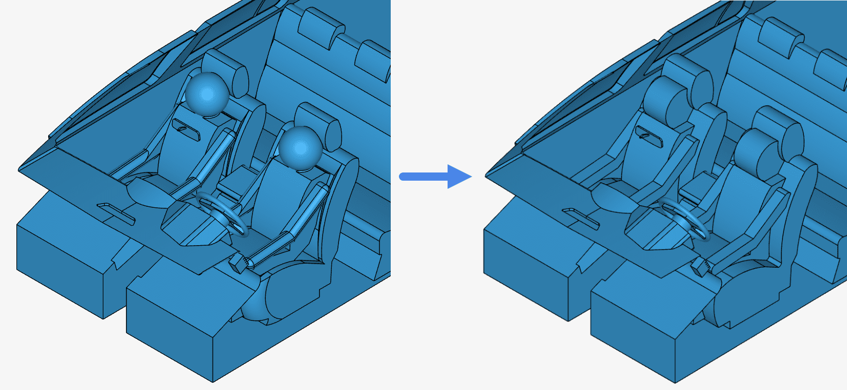
Some of the changes made were:
- Simplification of the heads and arms
- Closing of gaps between the heads and back of the passenger and the seats
- Removing details from the seats
In summary, they basically consisted of a simplification of shapes and closing up of gaps which were making it hard to generate a mesh with a low enough Non-orthogonality.
When generating a mesh with these adjustments to the geometry, the max Non-orthogonality dropped to a more acceptable level:
An option now is to apply some Non-orthogonal correctors if deemed necessary.
Note
If none of the above suggestions solved your problem, then please post the issue on our forum or contact us.


