This article explains the procedure to visualize the displacements of geometry parts in FEA simulations within SimScale’s online post-processor.
Solution
In finite element analysis (FEA), the parts of our geometries will usually move. This can be due to loads, translation, rotation, vibration, or thermal effects.
After a simulation is finished, the users can enter the post-processing section by clicking on either of these two options:
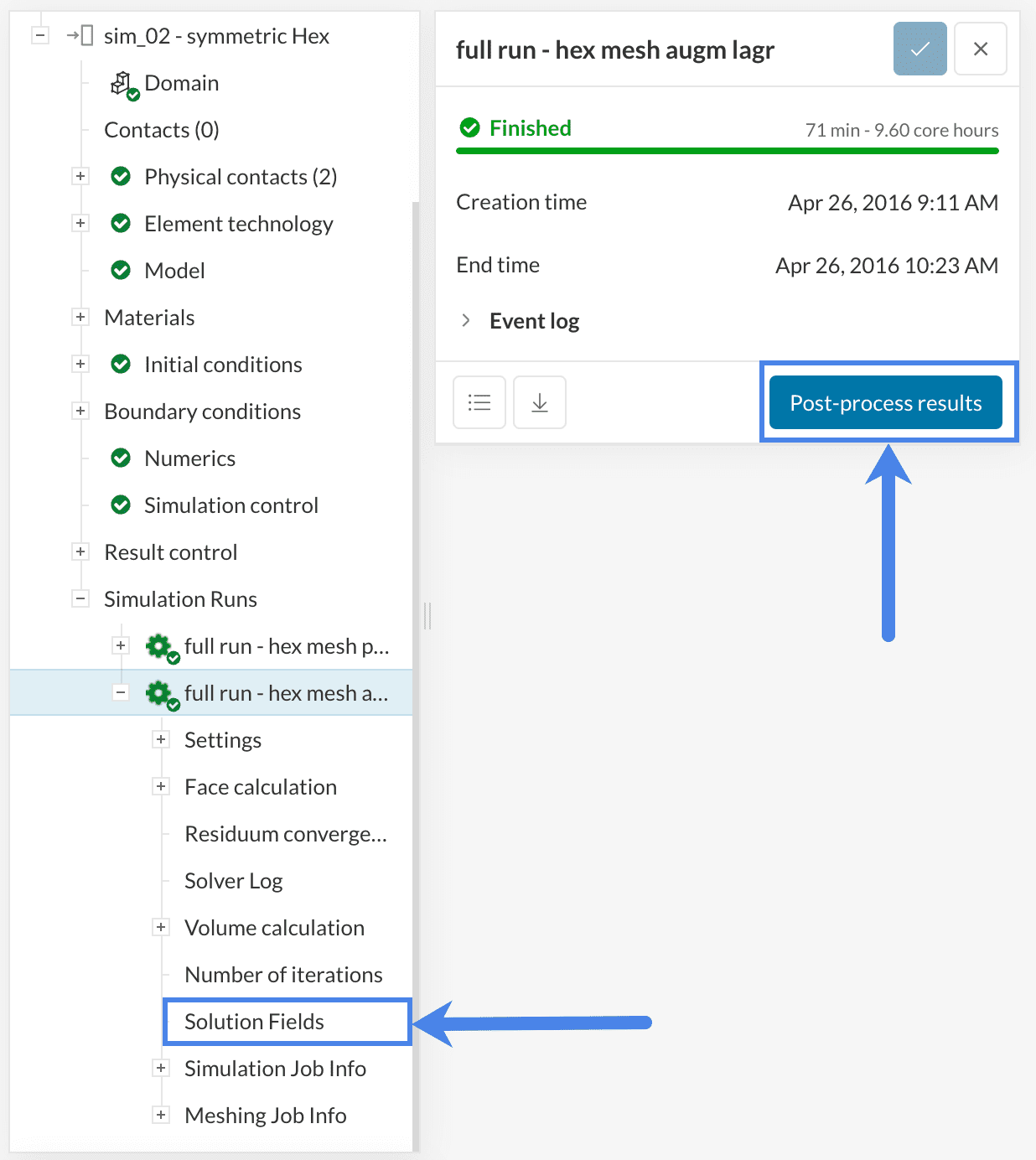
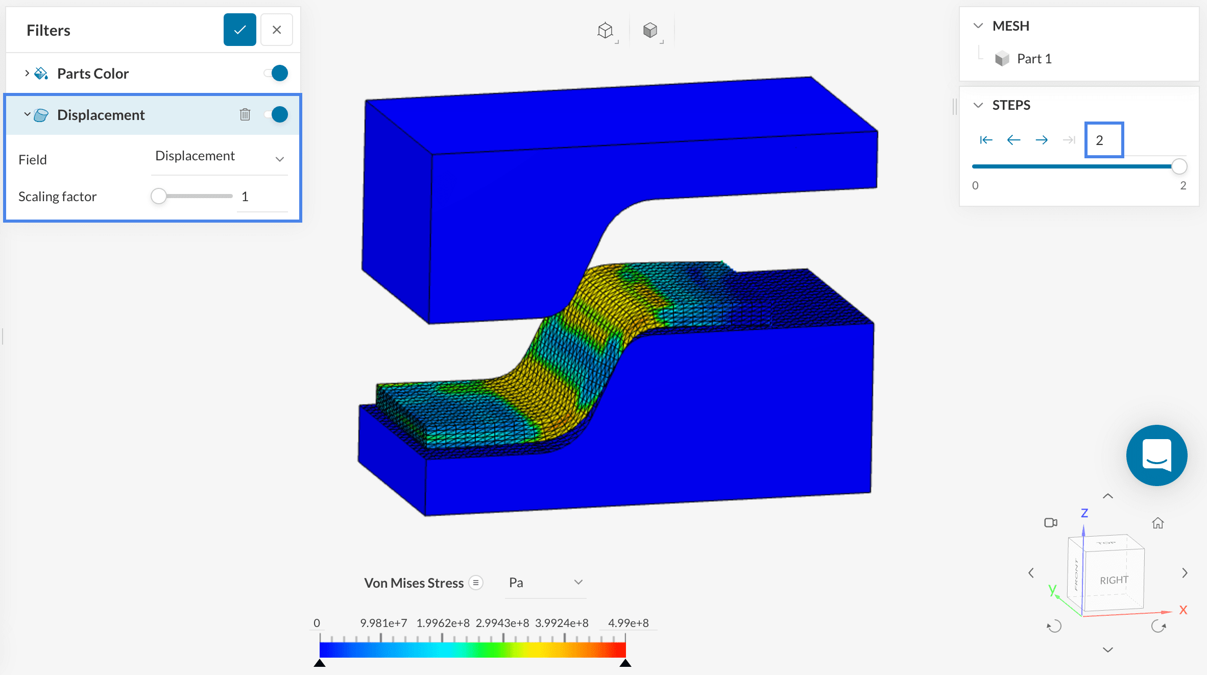
In the post-processor, a visual representation of displacements is enabled by default, with a scale of 1, at the latest timestep that was simulated:
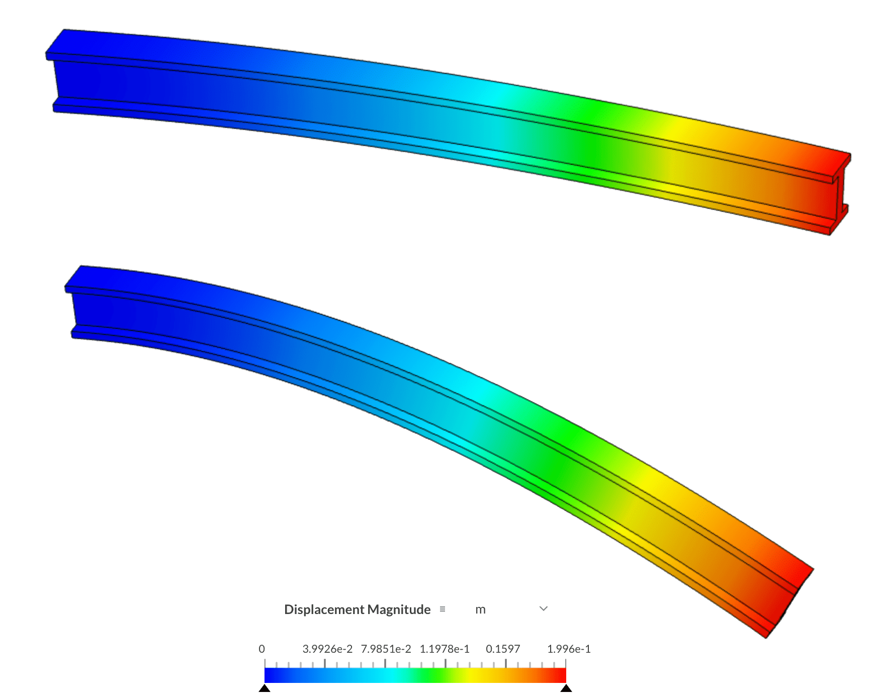
The user can also apply a scale factor to see the displacements more clearly, by entering it manually or adjusting the bar. As an example, here’s a straight beam fixed on one side, and subjected to a remote force on the other side, with a scale of 0.5, and a scale of 2:
It’s also possible to combine the visualization of displacements with the animations filter. This is particularly useful for nonlinear static, dynamic, and harmonic analysis types.
Find below an example of animation from a sheet metal stamping simulation. The displacements from the press and the sheet metal are shown:
For more information about the post-processing of finite element analysis simulations, make sure to check out the following pages:
Note
If none of the above suggestions solved your problem, then please post the issue on our forum or contact us.


