Documentation
This validation case describes a study performed in SimScale to demonstrate a method for modeling 3D voltage forced coils. The validation is based on the formulation studied by P.J. Leonard and D. Rodger\(^1\) in their research, “Voltage Forced Coils for 3D Finite Element Electromagnetic Models.”
In many electromagnetic devices, the magnetic field is generated by a coil or set of coils. When the terminal voltage is specified, rather than a known current, the current becomes an unknown variable that must be solved.
For this validation, the coil is treated as an ideal stranded coil. It is assumed that:
The study evaluates the formulation in two stages:
Two geometric variations were analyzed for this validation: a ‘Coil-with-Plates’ setup, where the coil is centered between two metallic sheets, and an ‘In-Air’ setup, which includes only the coil geometry.
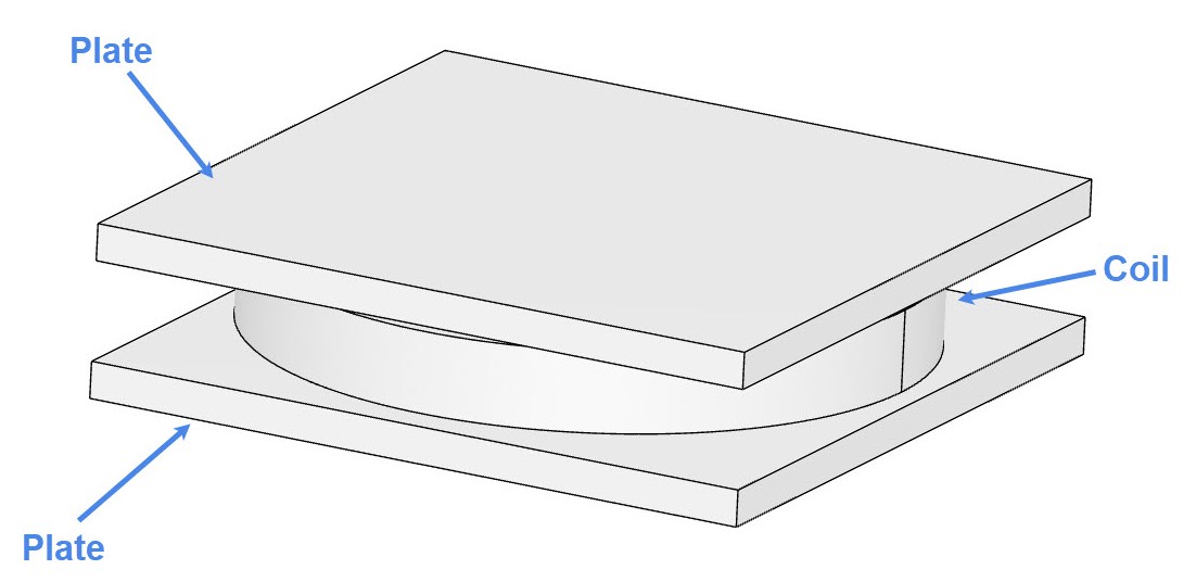
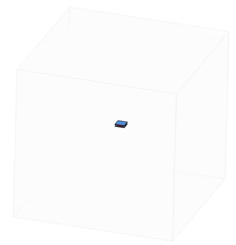
An air domain is created around the assembly in order to run the simulation. The resulting geometry is the following:
Analysis Type: Electromagnetics
Model: Time-Transient Magnetostatics
Mesh and Element Types: The meshes from this validation case were created in SimScale with the Standard meshing algorithm.
Find below an overview of the meshes used in this validation study:
| Mesh (With Plate) | Mesh Type | Nodes | Element Type |
| Coarse Mesh | Standard | 125364 | 3D tetrahedral |
| Moderate Mesh | Standard | 213707 | 3D tetrahedral |
| Fine Mesh | Standard | 545421 | 3D tetrahedral |
| Mesh (In Air) | Mesh Type | Nodes | Element Type |
| Coarse Mesh | Standard | 75131 | 3D tetrahedral |
| Moderate Mesh | Standard | 129543 | 3D tetrahedral |
| Fine Mesh | Standard | 327021 | 3D tetrahedral |
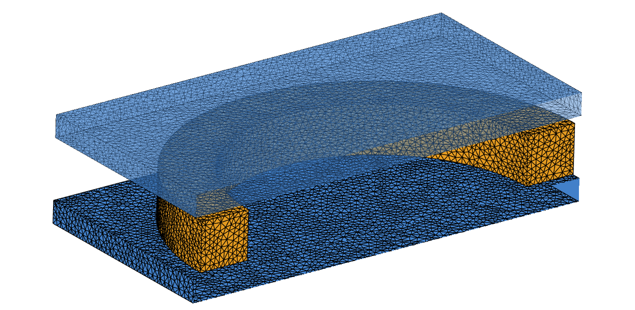
Figure 3 shows a cross section of how the finest mesh captures the surfaces of the assembly:
Material:
Coils:
Two coils with the same setup are present in this validation case.
Since a quarter model is used, the setup involves an open coil with the following settings:
The reference publication\(^1\) presents experimental data for the current on the coil.
A mesh sensitivity study was performed with a set of three meshes (Table 1 and 2), focusing on the current observed on the coil. Figures 4 and 5 show how the current evolves as more nodes are added to the mesh:
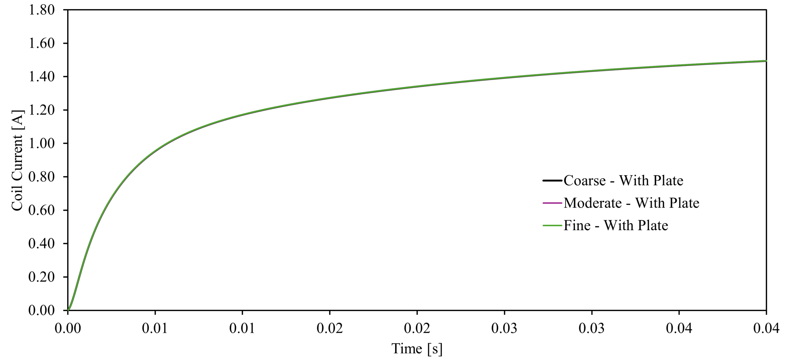
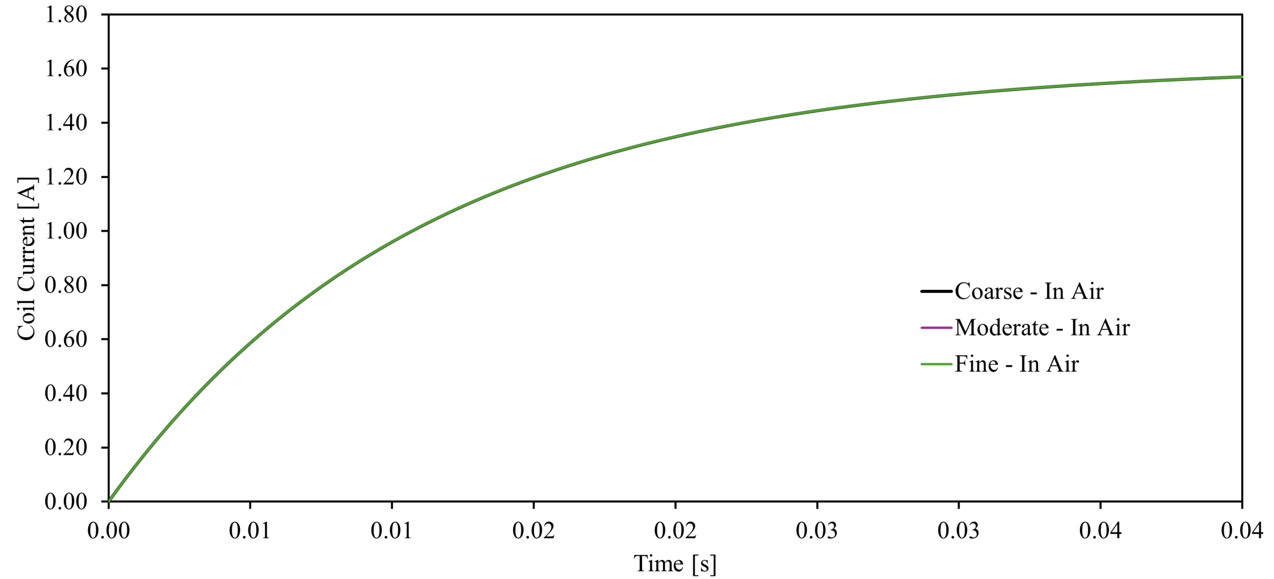
The sensitivity study shows great stability between the meshes, despite the great increase in mesh density, indicating mesh-independent results.
Figure 6 presents a comparison between the results obtained in SimScale and the experimental data reported by P.J. Leonard and D. Rodger\(^1\). The simulation demonstrates high fidelity and strong correlation with the experimental benchmarks across both tested environments:
The data shows a consistent trend, confirming that the SimScale Stranded Coil formulation effectively replicates the physical behavior of voltage-forced electromagnetic systems. This high degree of agreement validates the modeling approach for use in more complex, non-linear, or transient industrial applications.
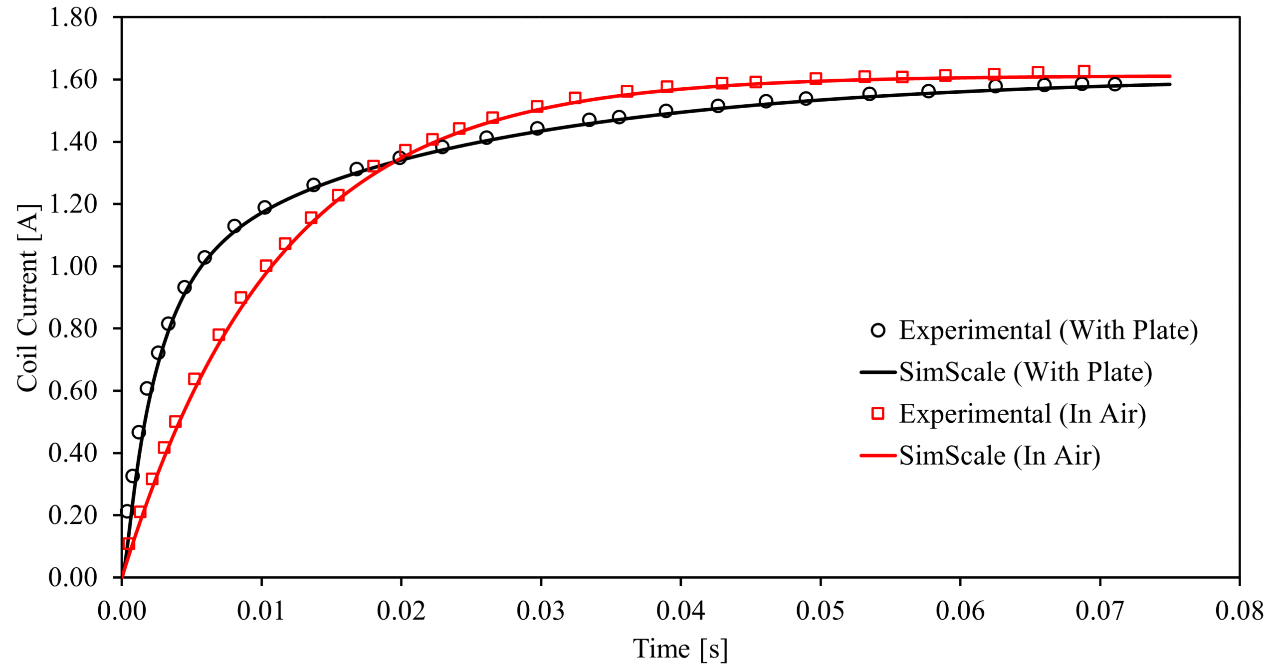
Figure 7 shows the current density in the plate with vectors to visualize the behavior of this variable inside the plate.
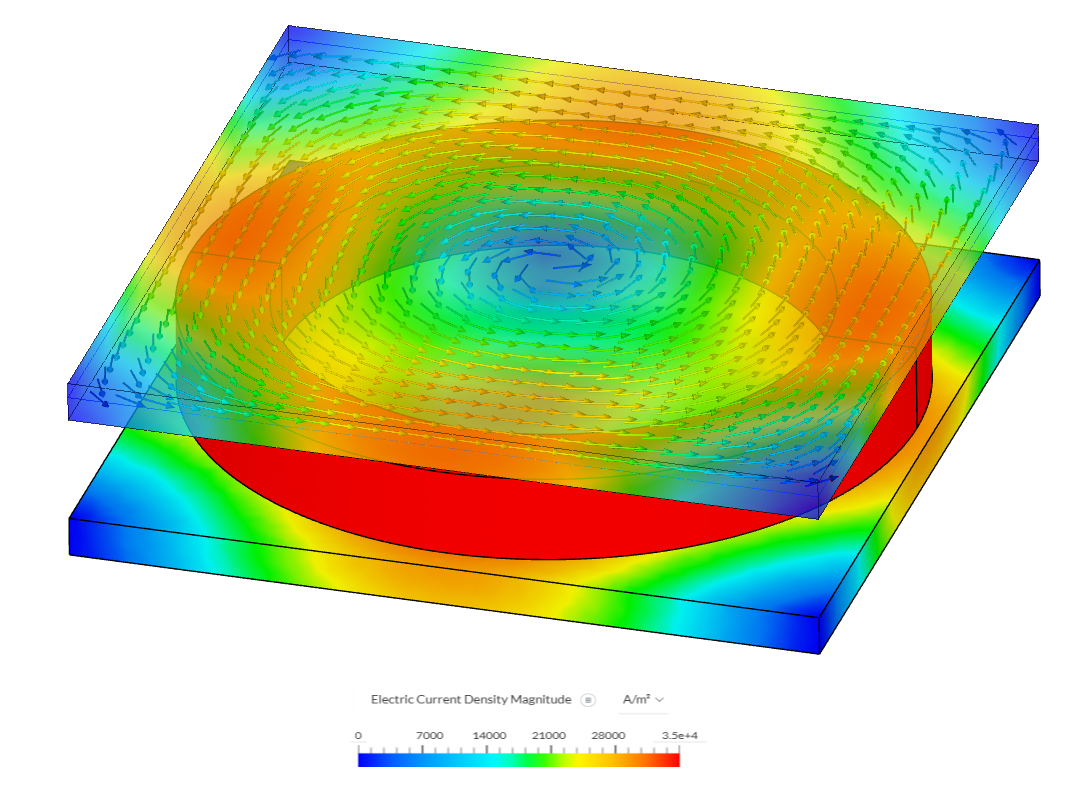
The simulation results show good agreement with trends that were measured for the currents on the coil.
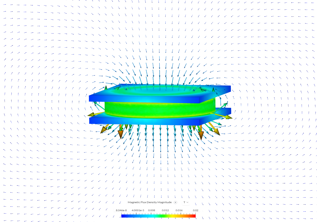
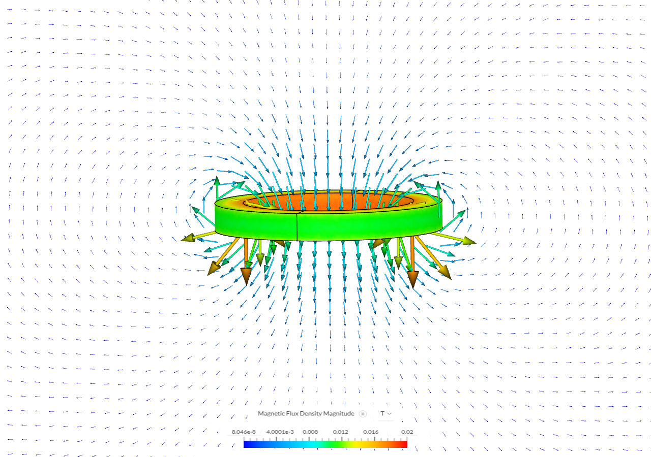
Figures 8 and 9 show the magnetic flux density for both cases, allowing visualization of the magnetic field vectors.
Last updated: March 6th, 2026
We appreciate and value your feedback.
Sign up for SimScale
and start simulating now