Validation Case: Thermal Stress Analysis of Polymeric Photo-Thermal Microactuator
This thermal stress analysis of a polymeric photo-thermal microactuator validation case belongs to thermomechanics. This test case aims to validate the following:
- Thermomechanical solvers
The simulation results of SimScale were compared to the analytical results presented in [Elbuken et al.]\(^1\).
Geometry
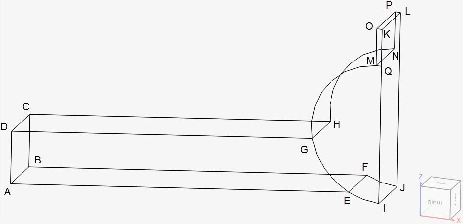
A total of 13 microactuator geometries are evaluated in this validation case. The base geometry is shown below:
The 13 geometries are divided into two groups. Using Figure 2 as a reference, for the group A geometries, the length L and width W of the microactuator remains constant, whereas the bending angle \(\theta\) varies.
For group B, the length L and bending angle \(\theta\) are constant, and the width W changes. For all geometries, the radius R and thickness of the microactuator, in the y-direction, remains constant. Due to symmetry, only half of the model was taken for the analysis.
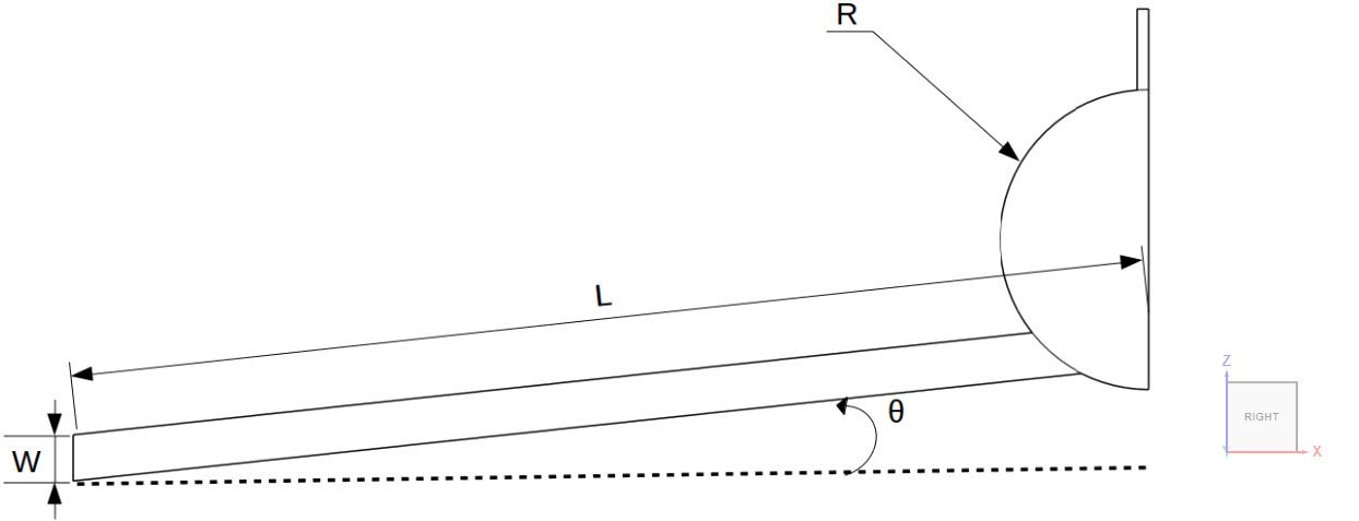
Table 1 provides an overview of the dimensions:
| Case | R \([\mu m]\) | Thickness in y-direction \([\mu m]\) | W \([\mu m]\) | L \([\mu m]\) | \(\theta\) [º] |
| A1 | 130 | 100 | 50 | 1000 | 6 |
| A2 | 130 | 100 | 50 | 1000 | 8 |
| A3 | 130 | 100 | 50 | 1000 | 10 |
| A4 | 130 | 100 | 50 | 1000 | 12 |
| A5 | 130 | 100 | 50 | 1000 | 14 |
| B1 | 130 | 100 | 30 | 700 | 6 |
| B2 | 130 | 100 | 40 | 700 | 6 |
| B3 | 130 | 100 | 50 | 700 | 6 |
| B4 | 130 | 100 | 60 | 700 | 6 |
| B5 | 130 | 100 | 70 | 700 | 6 |
| B6 | 130 | 100 | 80 | 700 | 6 |
| B7 | 130 | 100 | 90 | 700 | 6 |
| B8 | 130 | 100 | 100 | 700 | 6 |
Analysis Type and Mesh
Tool Type: Code Aster
Analysis Type: Thermomechanical analysis type
Mesh and Element Types: All meshes were created with the standard algorithm, using second-order elements. Table 2 presents a summary of the meshes:
| Case | Mesh Type | Nodes | Element Type |
| A1 | 2nd-order standard | 194853 | Standard |
| A2 | 2nd-order standard | 479747 | Standard |
| A3 | 2nd-order standard | 360734 | Standard |
| A4 | 2nd-order standard | 466753 | Standard |
| A5 | 2nd-order standard | 257295 | Standard |
| B1 | 2nd-order standard | 102941 | Standard |
| B2 | 2nd-order standard | 134074 | Standard |
| B3 | 2nd-order standard | 130987 | Standard |
| B4 | 2nd-order standard | 132192 | Standard |
| B5 | 2nd-order standard | 142016 | Standard |
| B6 | 2nd-order standard | 152533 | Standard |
| B7 | 2nd-order standard | 165596 | Standard |
| B8 | 2nd-order standard | 173364 | Standard |
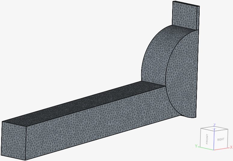
Find below the mesh used for case B8. It’s a standard mesh with second-order tetrahedral cells.
Simulation Setup
Material:
- Custom material – SU-8
- Material behavior: linear elastic
- \(E\) = 4 \(GPa\)
- \(\nu\) = 0.22
- \(\rho\) = 1200 \(kg/m³\)
- \(\kappa\) = 0.2 \(\frac {W}{m.K}\)
- Expansion coefficient = 5.2e-5 \(1/K\)
- \(T_0\) Reference temperature = 300 \(K\)
- Specific heat = 1500 \(\frac {J}{kg.K}\)
Boundary Conditions:
- Constraints
- Fixed support on face ABCD;
- \(d_x\) = 0 on face JIQKL.
- Temperature loads
- Fixed temperature value of 300 \(K\) on face ABCD.
- Heat flux loads
- Surface heat flux boundary condition of 9433.96 \(W/m²\) face IEGMQ.
- Convective heat flux boundary condition on all faces, except ABCD and JIQKL. The heat transfer coefficient is 10 \(\frac {W}{K.m^2}\) and the \(T_0\) reference temperature is 300 \(K\).
Reference Solution
The analytical solution is given by the equations presented in [Elbuken et al.]\(^1\).
Result Comparison
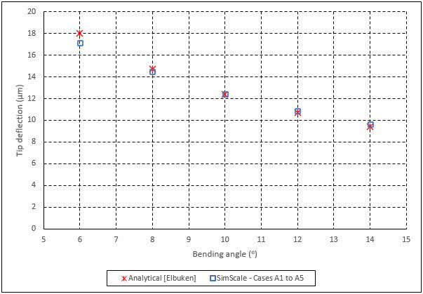
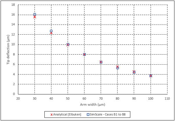
Find below the comparison between the analytical solution and SimScale results. The quantity measured is the displacement of the tip of the structure (face OPLK).
The first plot shows the results for cases A1 through A5:
Similarly, for cases B1 through B8, Figure 5 shows the result comparison:
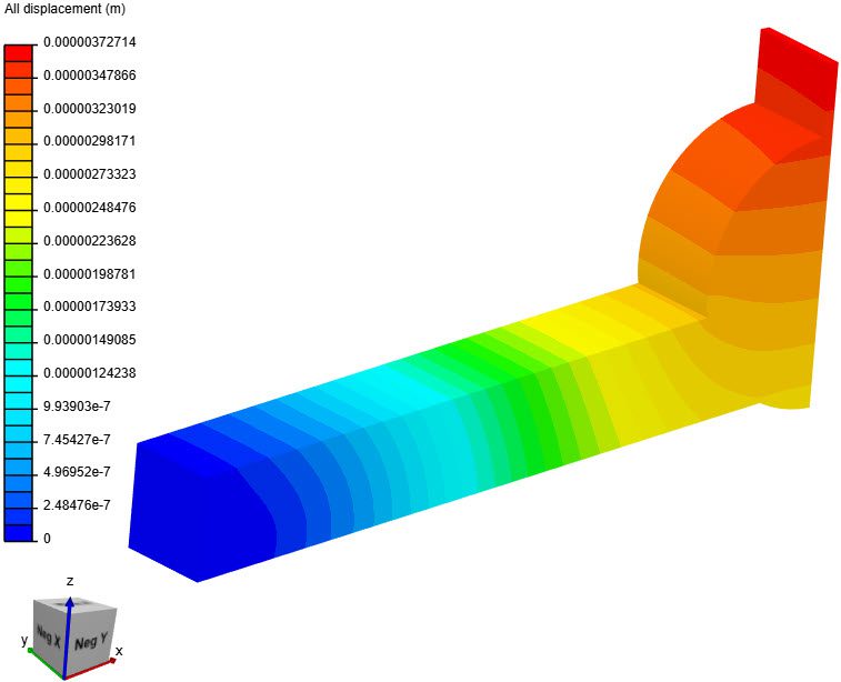
In Figure 6, we can see the displacement contours for case B8:
Last updated: February 8th, 2026
Did this article solve your issue?
How can we do better?
We appreciate and value your feedback.


