Documentation
The TEAM 24 validation case belongs to electromagnetics. This test case aims to validate the following parameters:
SimScale’s simulation results were compared to measured data presented in TEAM Workshop Problem 24\(^1\).
The geometry used in the TEAM 24 validation case is similar to a switched reluctance machine. The assembly contains 2 closed copper coils, a steel rotor, and a steel stator. For a total of 0.35 seconds of analysis, the torque on the rotor (around Z axis) and the current on the coils are analyzed.
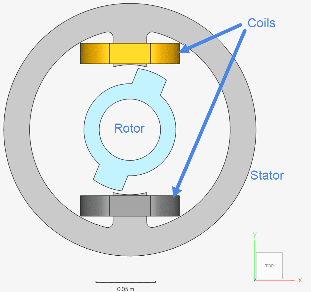
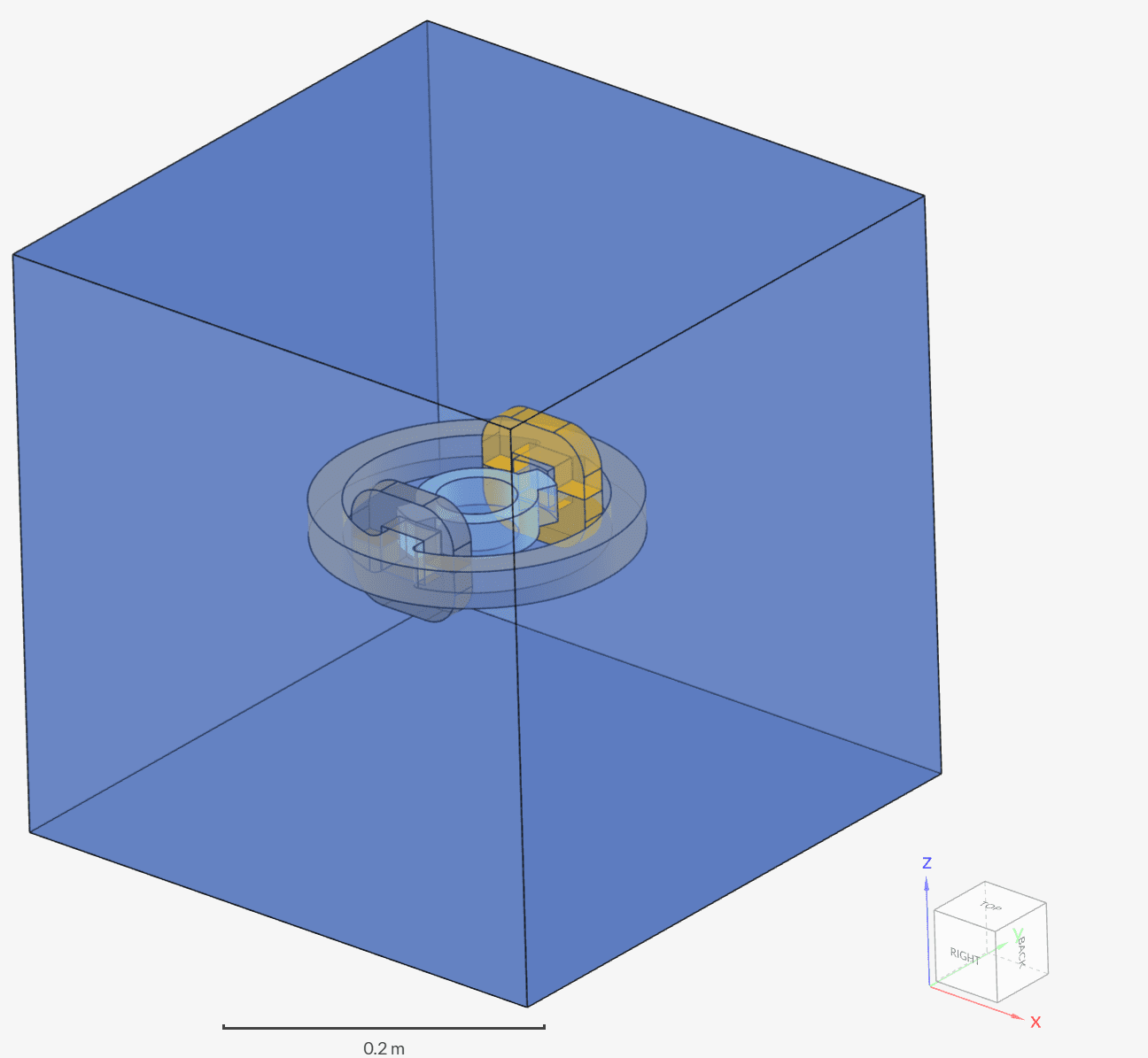
An air domain is created around the assembly in order to run the simulation. The resulting geometry is the following:
Analysis Type: Electromagnetics
Model: Time-Transient Magnetostatics
Mesh and Element Types: The meshes from this validation case were created in SimScale with the Standard meshing algorithm.
Find below an overview of the meshes used in this validation study:
| Mesh | Mesh Type | Nodes | Element Type |
| Coarse Mesh | Standard | 357297 | 3D tetrahedral |
| Moderate Mesh | Standard | 790589 | 3D tetrahedral |
| Fine Mesh | Standard | 2350806 | 3D tetrahedral |
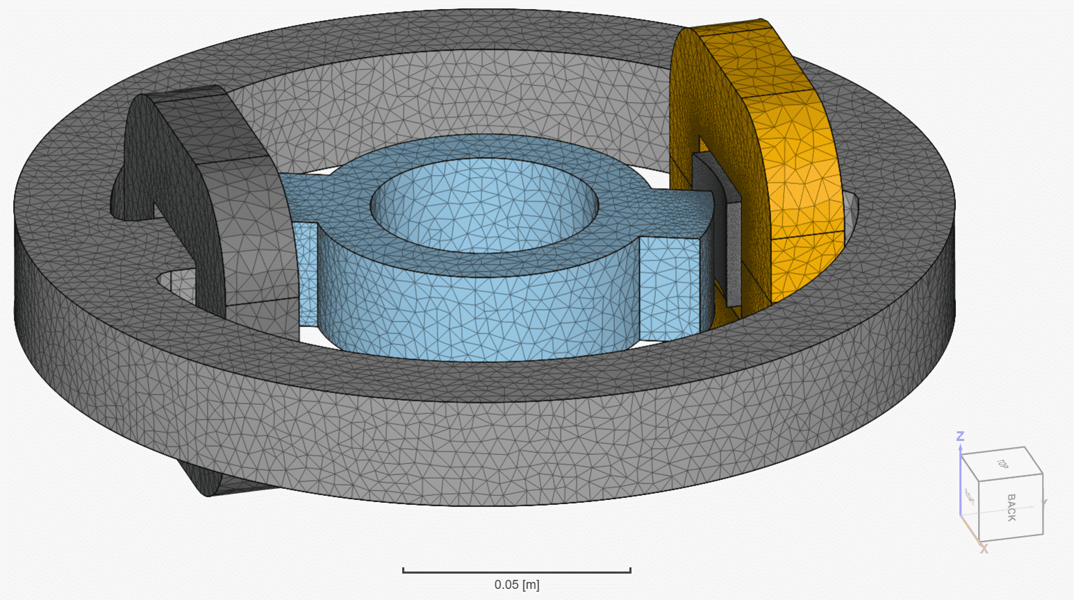
Figure 3 shows how the finest mesh captures the surfaces of the assembly:
Material:
Coils:
Two coils with the same setup are present in this validation case.
Since a quarter model is used, the setup involves an open coil with the following settings:
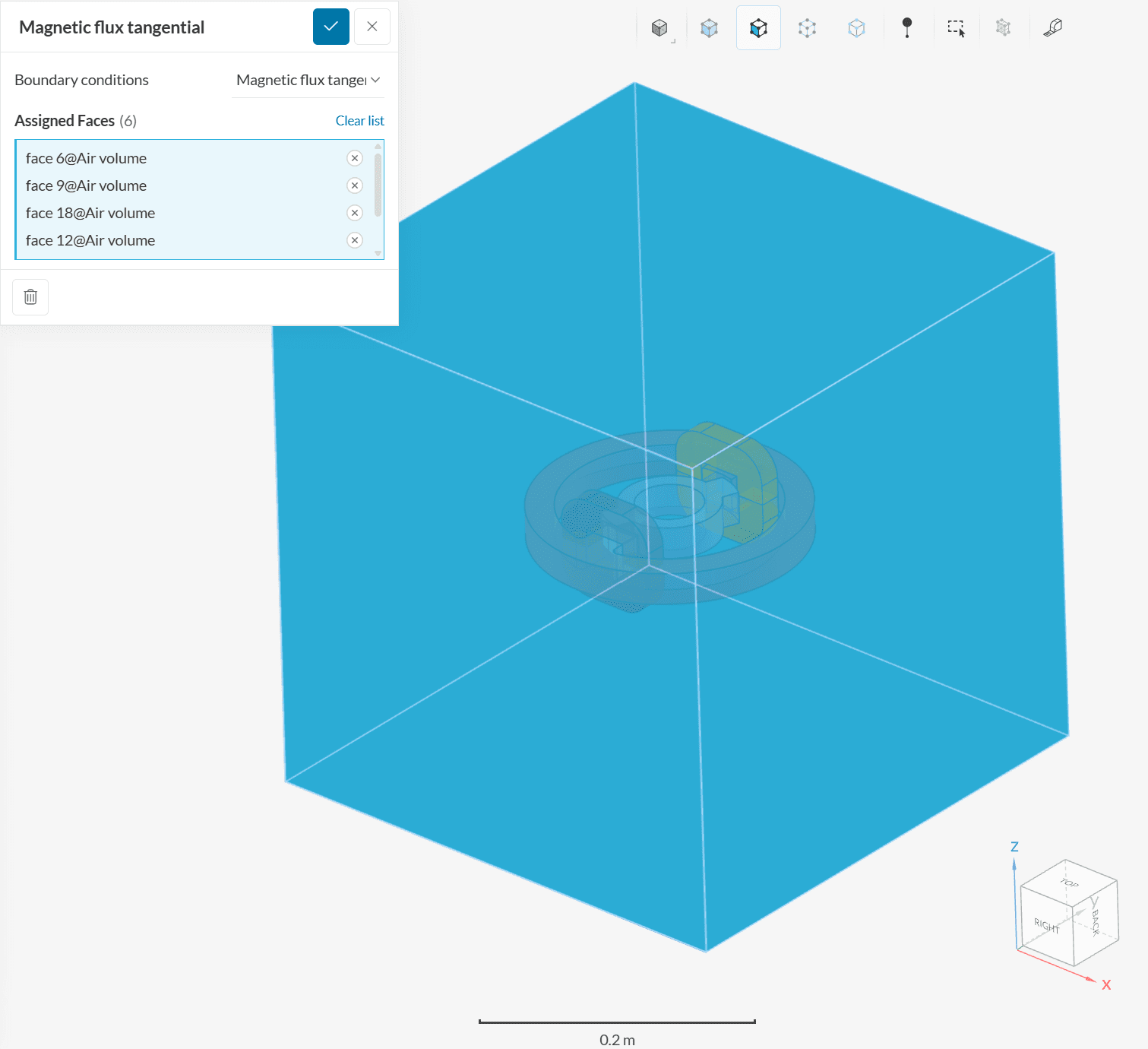
Boundary Conditions:
All 6 external air volume faces receive a magnetic flux tangential boundary condition.
The reference publication\(^1\) presents experimental data for torque on the rotor due to the coils, as well as the currents on the coil.
A mesh sensitivity study was performed with a set of three meshes, focusing on the torques observed on the rotor. The figure below shows, for the last timestep, how the torque around the Z direction evolves as more nodes are added to the mesh:
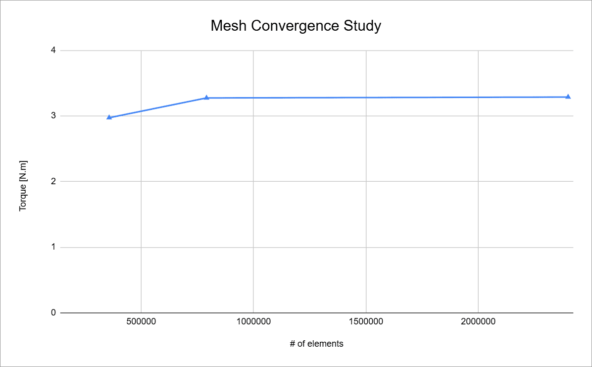
The sensitivity study shows great stability between the moderate and fine meshes, despite the great increase in mesh density, indicating mesh-independent results.
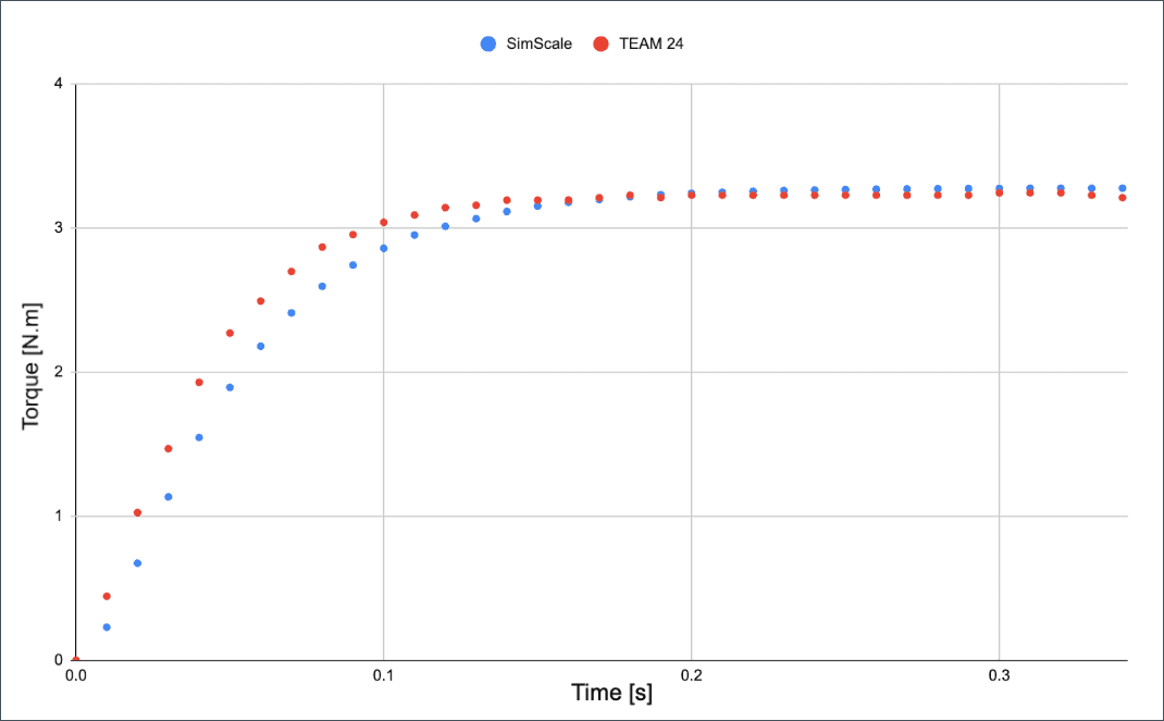
Find below a comparison between the fine mesh results and experimental data\(^1\) for torques on the rotor around the Z-direction:
As previously discussed, the currents on the coils have also been compared against experimental data\(^1\):
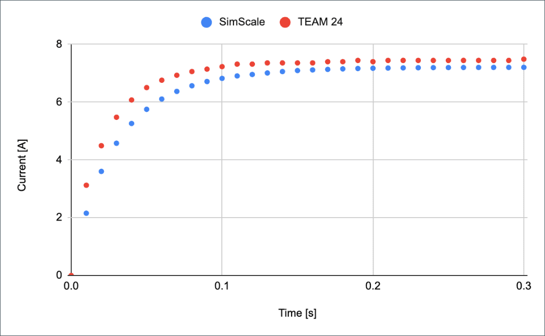
The simulation results shows good agreement with trends that were measured for torques on the rotor and currents on the coils.
Last updated: August 11th, 2025
We appreciate and value your feedback.
Sign up for SimScale
and start simulating now