Documentation
The TEAM 20 validation case belongs to electromagnetics. This test case aims to validate the following parameters:
SimScale’s simulation results were compared to measured data presented by Nakata et al.\(^1\) and further expanded in TEAM Workshop 3\(^2\).
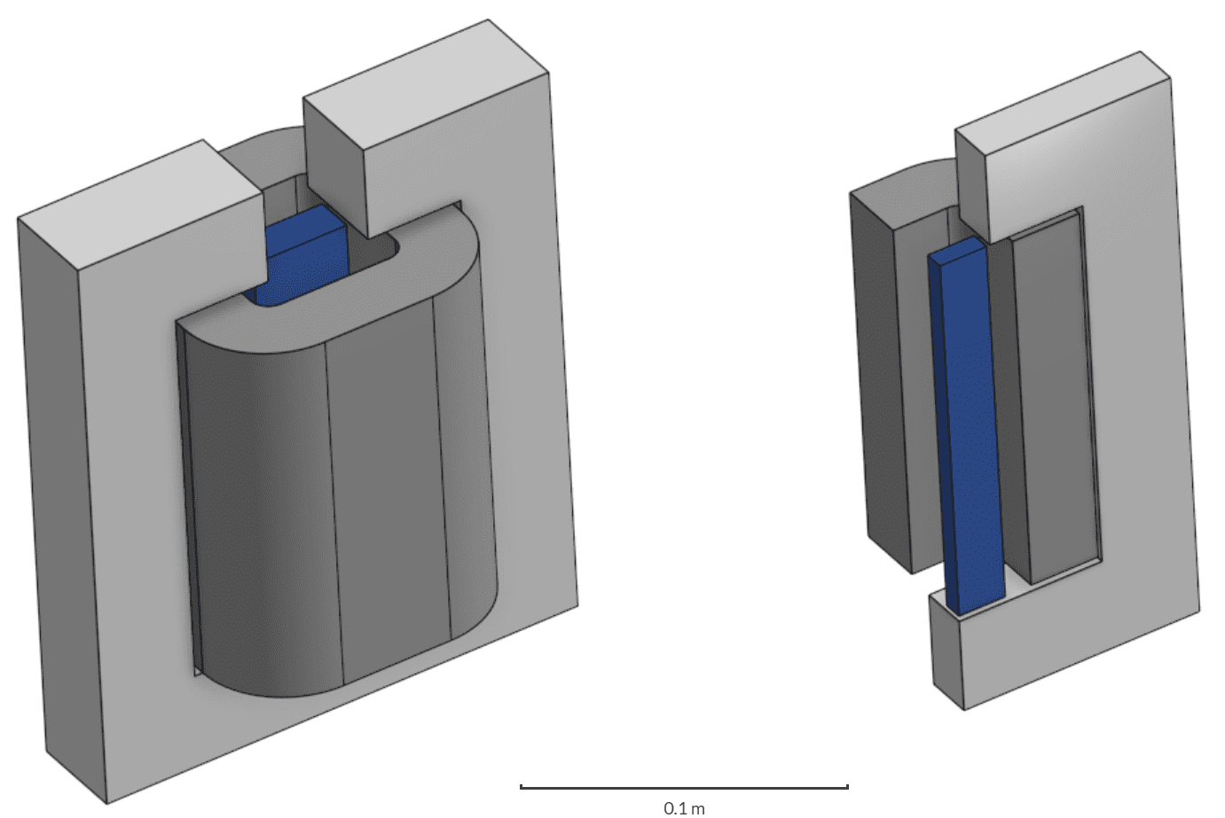
A solenoid with a steel core and plunger pole is analyzed using the magnetostatics module in SimScale. In this project, a current applied to the coil generates a force onto the pole, which is monitored in the results.
The image below shows the complete assembly (on the left) and the quarter solenoid model used as reference in this validation project (on the right):
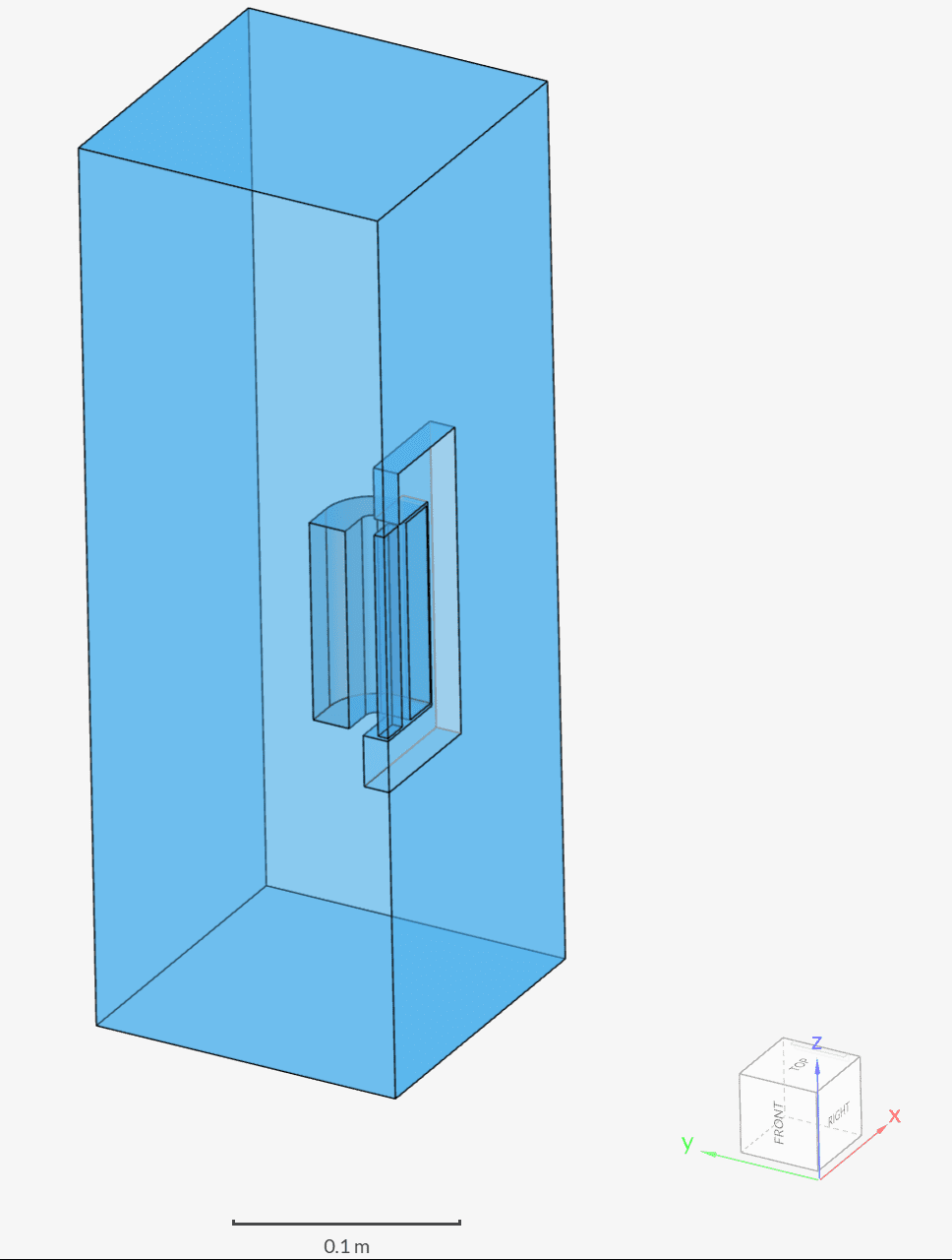
Besides the three solid parts, an additional air domain is created around the solenoid, resulting in the following geometry:
Analysis Type: Electromagnetics
Mesh and Element Types: The meshes from this validation case were created in SimScale with the Standard meshing algorithm.
Find below an overview of the meshes used in this validation study:
| Mesh | Mesh Type | Nodes | Element Type |
| Coarse Mesh | Standard | 91765 | 3D tetrahedral |
| Moderate Mesh | Standard | 797780 | 3D tetrahedral |
| Fine Mesh | Standard | 2076159 | 3D tetrahedral |
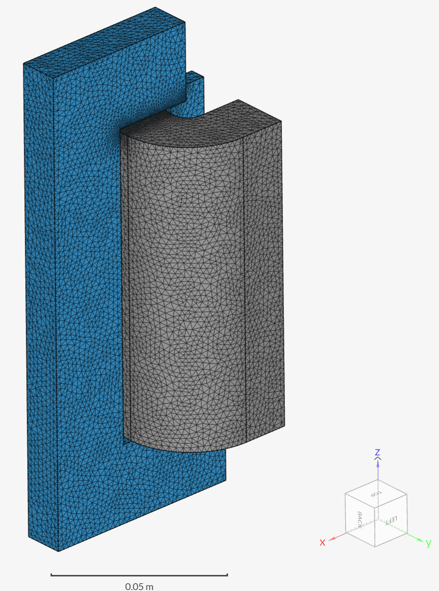
Figure 3 shows the fine mesh aspect on the surfaces of the solenoid:
Material:
Coils:
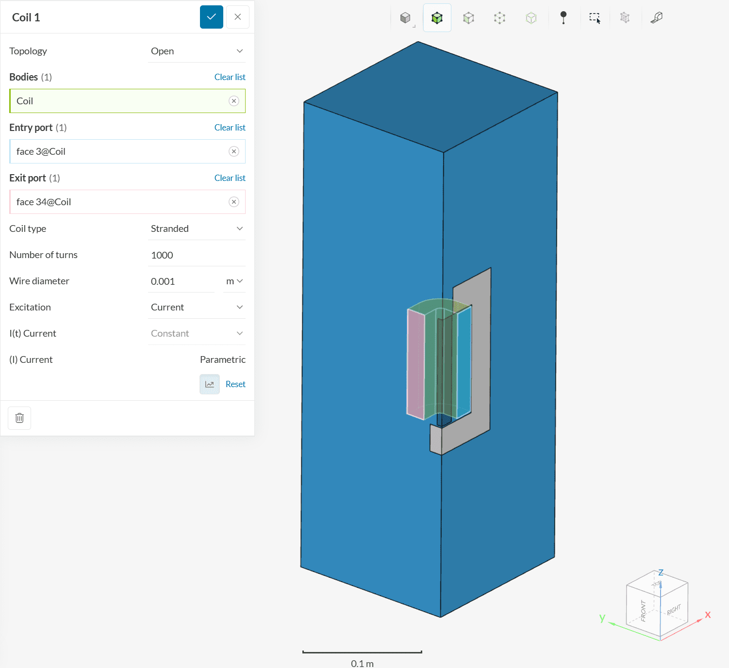
The TEAM 20 validation case involves coils with 1000, 3000, 4500, and 5000 ampere-turns.
Since a quarter model is used, the setup involves an open coil with the following settings:
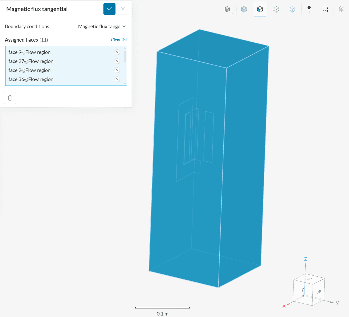
Boundary Conditions:
All external faces receive a magnetic flux tangential boundary condition.
Initial experimental results for forces in the Z-direction on the steel pole were presented by Nakata et al.\(^1\) and further expanded in TEAM Workshop 3\(^2\). When considering the full CAD model, the reference solution is:
| Ampere-turns | \(F_z\) on the steel pole \([N]\) |
| 1000 | 8.1 |
| 3000 | 54.4 |
| 4500 | 75.0 |
| 5000 | 80.1 |
A mesh sensitivity study was performed with a set of three meshes: a coarse mesh with 91765 nodes, a moderate mesh with 797780 nodes, and a fine mesh with 2076159 nodes.
Since the validation case uses a quarter model, the forces in the Z direction from the simulation were multiplied by 4 and then compared against the reference results.
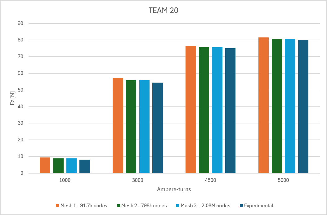
For all four studies, the results between the moderate and fine mesh shifted less than 0.15%, indicating great stability at these mesh densities.
Table 3 compares the experimental data against the fine mesh results:
| Ampere-turns | Experimental \(F_z\) \([N]\) | Fine Mesh \(F_z\) \([N]\) | Error [%] |
| 1000 | 8.1 | 8.8 | 8.7 |
| 3000 | 54.4 | 55.9 | 2.7 |
| 4500 | 75.0 | 75.6 | 0.8 |
| 5000 | 80.1 | 80.7 | 0.8 |
The simulation results showed good correspondence with the reference data, also highlighting the importance of a mesh sensitivity study in gaining understanding and confidence in simulation results.
References
Last updated: August 11th, 2025
We appreciate and value your feedback.
Sign up for SimScale
and start simulating now