Validation Case: Fixed Beam Under Gravitational Load
This bonded contact gravitational load validation case belongs to solid mechanics. This test case aims to validate the following parameter:
- Gravitational load
The simulation results of SimScale were compared to the analytical results derived from [Roark]\(^1\).
Geometry
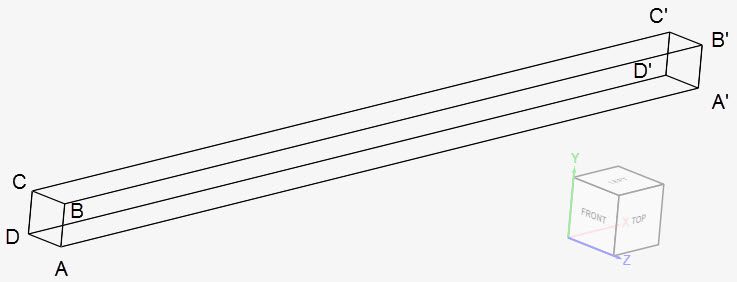
Two beam geometries are used for this gravitational load validation. They have a cross-section of 0.05 x 0.05 \(m^2\) and 1 \(m\) length (l). The first one consists of unrotated beam geometry, shown below:
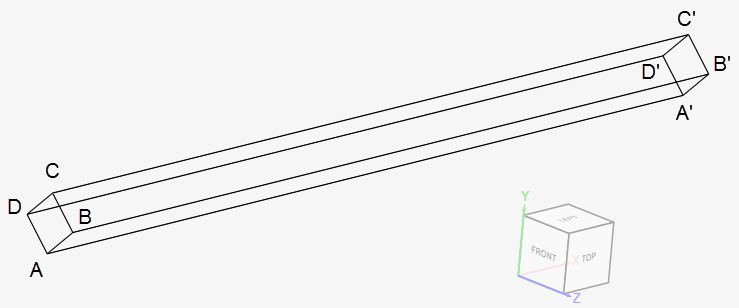
The second geometry is rotated 45º around the positive x-axis:
The coordinates for the points in the first geometry are as tabulated below:
| A | B | C | D | A’ | B’ | C’ | D’ | |
| x | 0 | 0 | 0 | 0 | 1 | 1 | 1 | 1 |
| y | 0 | 0.05 | 0.05 | 0 | 0 | 0.05 | 0.05 | 0 |
| z | 0.05 | 0.05 | 0 | 0 | 0.05 | 0.05 | 0 | 0 |
Similarly, for the rotated geometry, we have:
| A | B | C | D | A’ | B’ | C’ | D’ | |
| x | 0 | 0 | 0 | 0 | 1 | 1 | 1 | 1 |
| y | -0.03536 | 0 | 0.03536 | 0 | -0.03536 | 0 | 0.03536 | 0 |
| z | 0.03536 | 0.0707 | 0.03536 | 0 | 0.03536 | 0.0707 | 0.03536 | 0 |
Analysis Type and Mesh
Tool Type: Code Aster
Analysis Type: Linear static
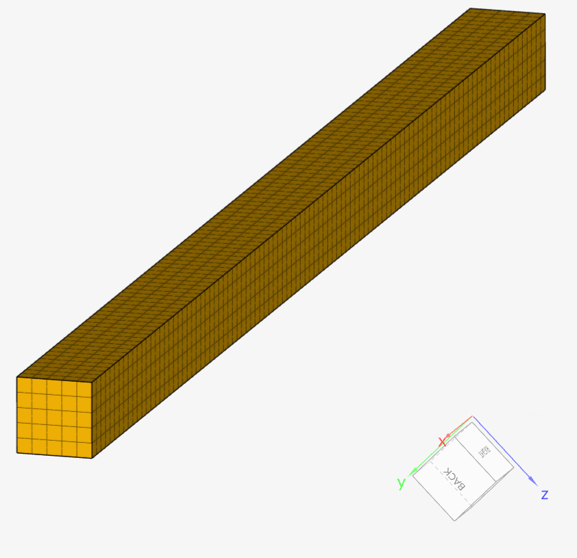
Mesh and Element Types: All meshes were created in SimScale with a controlled extrusion mesh refinement with the standard algorithm. The resulting meshes are fully hexahedral, with meshes used for cases C and D equivalent to those used in cases A and B, respectively, but rotated by 45 degrees.
| Case | Geometry | Mesh Type | Number of Nodes | Element Type |
| (A) | Beam – original | Standard – hexahedral cells | 3636 | 1st order |
| (B) | Beam – original | Standard – hexahedral cells | 13296 | 2nd order |
| (C) | Beam – rotated | Standard – hexahedral cells | 3636 | 1st order |
| (D) | Beam – rotated | Standard – hexahedral cells | 13296 | 2nd order |
Find below the mesh used for case D. It’s a hexahedral, extruded mesh with second-order cells.
Simulation Setup
Material:
- Steel (linear elastic)
- \(E\) = 205 \(GPa\)
- \(\nu\) = 0.28
- \(\rho\) = 7870 \(kg/m³\)
Boundary Conditions:
- Constraints
- Fixed support on face ABCD.
- Gravity (defined under model):
- Cases A and B: 9.81 \(m/s²\) in the negative z-direction (0, 0, -1);
- Cases C and D: 9.81 \(m/s²\) rotated 45º around the positive x-direction (0, 1, -1)
Reference Solution
Converting the gravitational load to a line load \((w_a)\):
$$w_{a}l = V.\rho.g \tag {1}$$
Solving \((1)\), we have:
$$w_{a}=193.01175\ N/m \tag {2}$$
The moment of inertia \(I\) is given by:
$$I = \frac {b.h^3}{12} = 5.20833⋅10^{−7}\ m^4 \tag {3}$$
The equation (4) below is derived from [Roark]\(^1\)
$$y(l) = -\frac{w_a l^4}{8 E I} = -2.2597 \cdot 10^{-4}\ m \tag {4}$$
Result Comparison
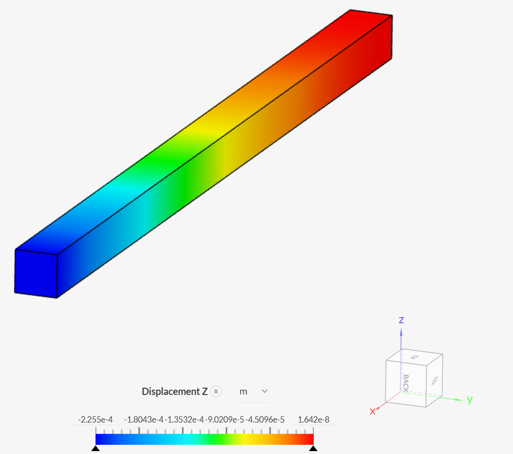
The table below shows the SimScale results for the displacement at the free end (face A’B’C’D’) in the gravity direction. Results are compared to the analytical solution by [Roark].
| Case | Quantity | [Roark] | SimScale | Error (%) |
| (A) | Displacement at the free end \([m]\) | -2.2597e-4 | -2.2075e-4 | -2.31 |
| (B) | Displacement at the free end \([m]\) | -2.2597e-4 | -2.2555e-4 | -0.19 |
| (C) | Displacement at the free end \([m]\) | -2.2597e-4 | -2.2075e-4 | -2.31 |
| (D) | Displacement at the free end \([m]\) | -2.2597e-4 | -2.2555e-4 | -0.19 |
Inspecting the displacements in the z-direction for case B:
References
- W. C. YOUNG, R. G. BUDYNAS. Roark’s Formulas for Stress and Strain. Seventh Edition. McGraw-Hill. 2002. p. 191.
Last updated: April 3rd, 2026
Did this article solve your issue?
How can we do better?
We appreciate and value your feedback.


