Validation Case: Butterfly Valve with Multi-purpose solver
This validation case belongs to fluid dynamics and the aim of this case is to validate the following parameters inside a pipe with a butterfly valve:
- Pressure drop using the Multi-purpose solver in SimScale
The simulation results of SimScale were compared to the results presented in the study done by Song, Xue Guan, and Park, Young Chui with the title “Numerical Analysis of Butterfly Valve – Prediction of Flow Coefficient and Hydrodynamic Torque Coefficient“\(^1\).
Geometry
The model used in this validation case is a pipe with a disc-shaped butterfly valve inside, which can be seen below:
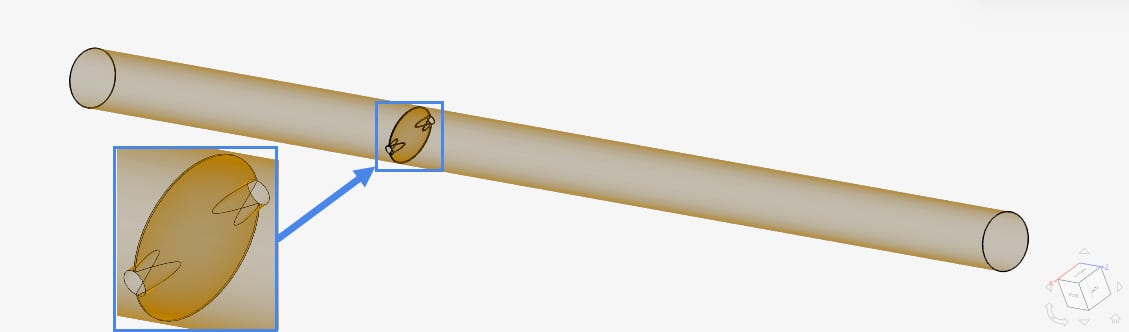
The dimensions of the pipe can be seen in the table below:
| Dimension | Value \([m]\) |
| Upstream length | 14.4 |
| Downstream length | 27 |
| Valve & pipe diameter (D) | 1.8 |
| Valve maximum thickness | 0.36 |
9 variants of valve opening angles ranging from 20° to 85° were used as a comparison to the reference study.
Analysis Type and Mesh
Analysis Type: Steady-state, Multi-purpose with K-Epsilon turbulence model
Mesh and Element Types: The mesh was created with SimScale’s Multi-purpose mesh type.
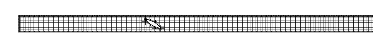
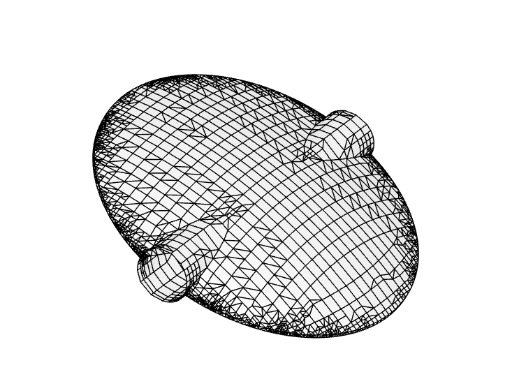
Mesh Sensitivity
The Multi-purpose meshing algorithm with hexahedral cells was used to generate the mesh. For this simulation, refinement level 8 was chosen for the comparison of different valve openings.
| Mesh Type | Number of cells | Element Type |
| Automatic Level 8 | 99000 | 3D Tetrahedral/Hexahedral |
Simulation Setup
Fluid:
- Water
- Kinematic viscosity \((\nu)\): 9.338e-7 \(m^2/s\)
- Density \((\rho)\): 997.3 \(kg/m^3\)
Boundary Conditions:
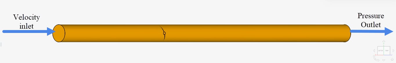
The boundary conditions are the same for all opening angles and were assigned as shown in Table 3:
| Boundary Condition | Value |
| Velocity inlet | 3 \(m/s\) |
| Pressure outlet | 0 \(Pa\) |
| No-slip wall | Pipe walls and valve surface |
Reference Solution
The reference solution for the flow coefficient and the torque coefficient is given in the following formulae:
Flow coefficient:
$$c_v = Q \sqrt{\frac{S_g}{\Delta P}} \tag{1}$$
where:
- \(c_v\): flow coefficient
- \(Q\): flow discharge \((GPM-Gallons\,per\,minute)\)
- \(\Delta P\): pressure drop \((psi)\)
- \(S_g\): specific gravity of water
Torque coefficient:
$$c_t = \frac{T(x)}{\Delta P \times d^3} \tag{2}$$
where:
- \(c_t\): torque coefficient
- \(T(x)\): torque in the x-axis \((N.m)\)
- \(\Delta P\): pressure drop \((psi)\)
- \(d\): diameter of pipe \((in)\)
Result Comparison
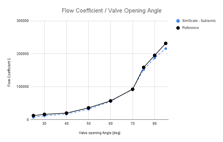
Comparison of the flow coefficient obtained from SimScale against the reference results obtained from [1] is given below:
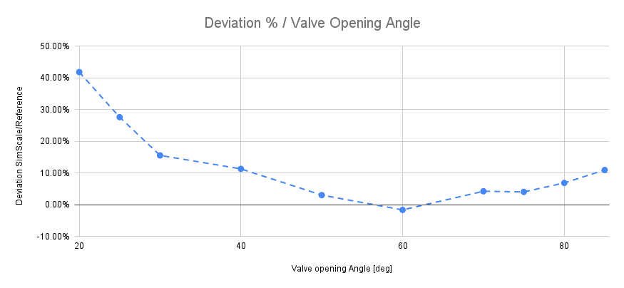
Deviation to Reference
Deviation of the results gained from SimScale in comparison to the results obtained from [1] can be seen in Figure 6. The deviation gets very close to the reference results for the opening angle from 50-70 degrees. It has to be noted that small valve opening angles are deviating highly, which is expected according to Song, Xue Guan, and Park, Young Chui\(^1\).
However, it must be noticed that at valve opening smaller than 20 degrees, the minimum error between CFX simulation and experimental data reach to 49.27958%.
Song, Xue Guan and Park, Young Chui Reference [1]
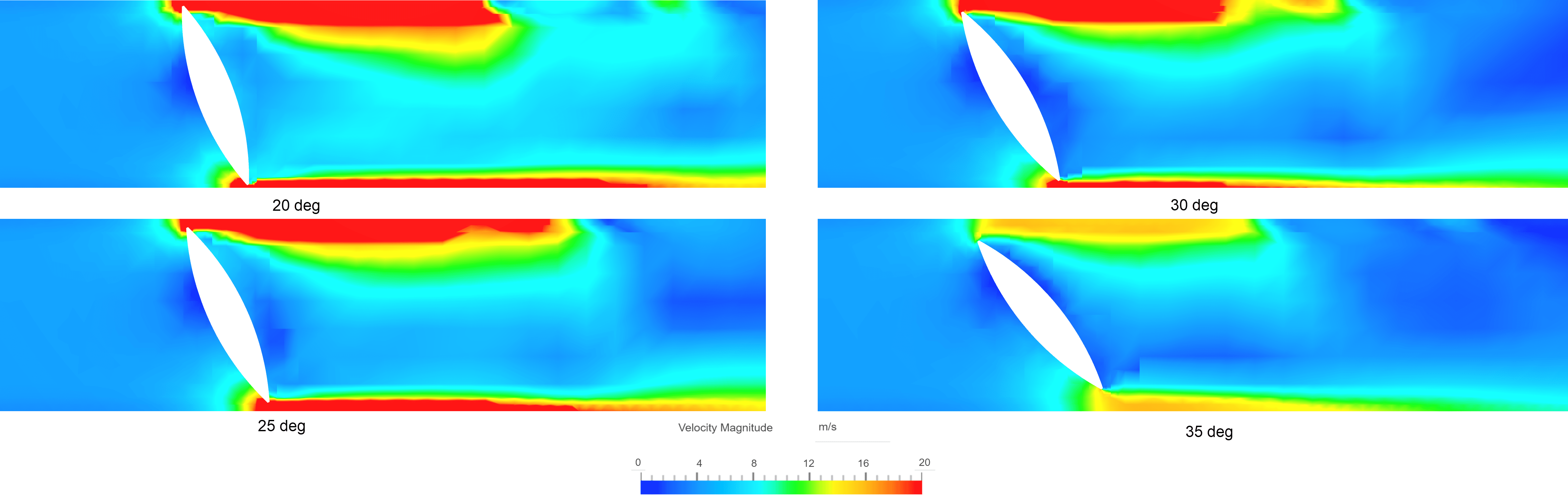
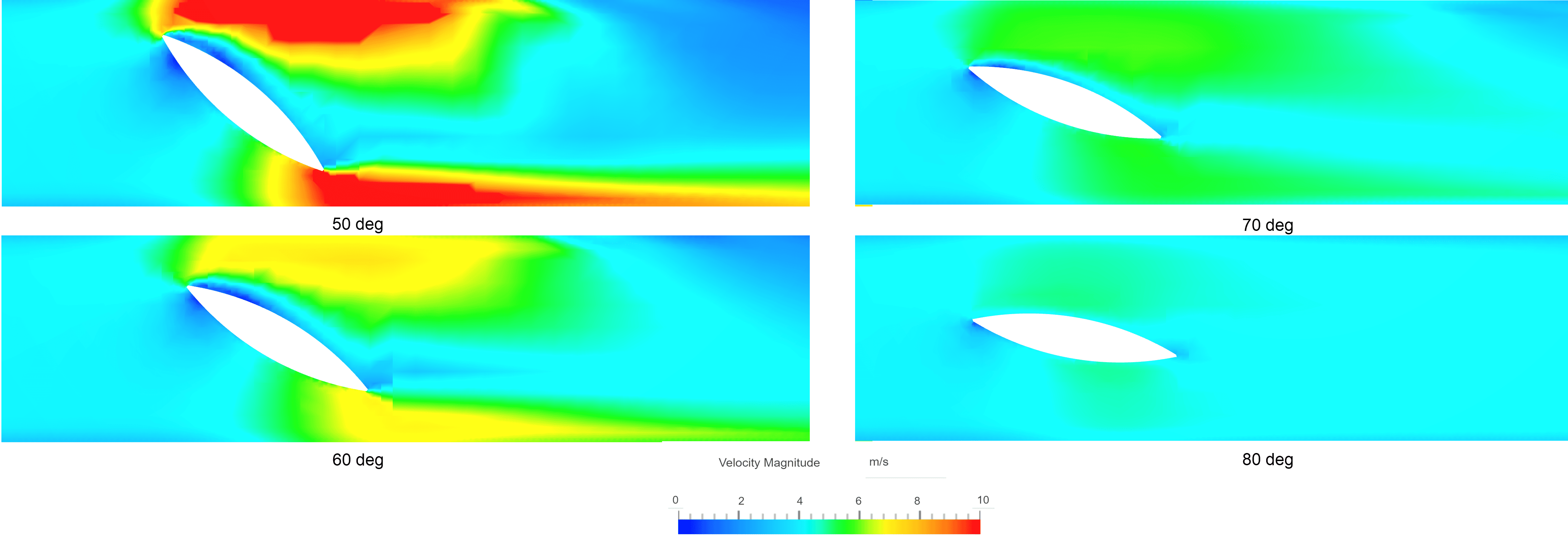
The flow contours inside the pipe when the valve is opened at the simulated opening angles as observed in our online post-processor:
Note
If you still encounter problems validating you simulation, then please post the issue on our forum or contact us.
Last updated: September 23rd, 2024
Did this article solve your issue?
How can we do better?
We appreciate and value your feedback.


