Validation Case: Bonded Contact on a Quarter Shaft
This bonded contact validation case belongs to solid mechanics. This test case aims to validate the following parameter:
- Bonded contact
The simulation results obtained with SimScale were compared to the analytical results presented in [Roark]\(^1\).
Geometry
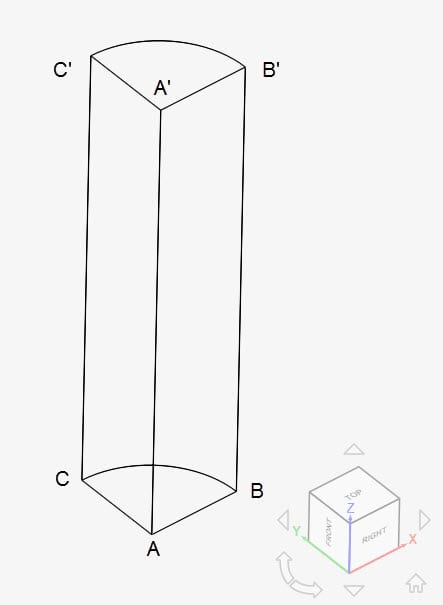
Two geometries are used for this bonded contact validation. The first one consists of a quarter shaft. Radius is 0.1 \(m\) and length is 0.5 \(m\):
The second geometry has the same dimensions, however, it is split exactly in half, between the ABC and A’B’C’ planes:
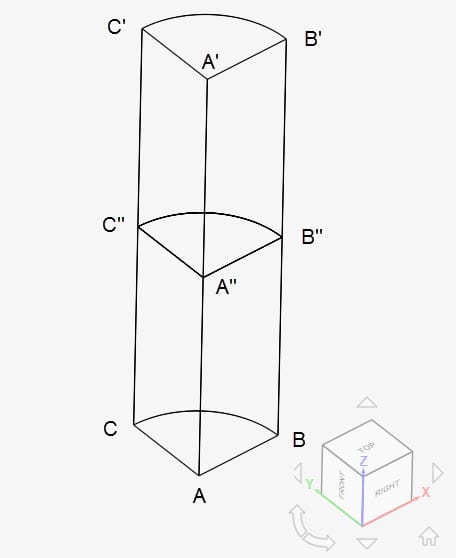
The 3D geometry is a 90\(^0\) section of a cylinder with dimensions as tabulated below:
| A | B | C | A’ | B’ | C’ | A” | B” | C” | |
| x | 0 | 0.1 | 0 | 0 | 0.1 | 0 | 0 | 0.1 | 0 |
| y | 0 | 0 | 0.1 | 0 | 0 | 0.1 | 0 | 0 | 0.1 |
| z | 0 | 0 | 0 | 0.5 | 0.5 | 0.5 | 0.25 | 0.25 | 0.25 |
Analysis Type and Mesh
Tool Type: Code Aster
Analysis Type: Linear static
Mesh and Element Types: The meshes for Cases A through D were created in SimScale. The standard algorithm was used.
| Case | Geometry | Element Type | Number of Nodes | Element Technology |
| (A) | Quarter Shaft | 1st Order Tetrahedral | 8660 | Standard |
| (B) | Quarter Shaft – Split | 1st Order Tetrahedral | 8846 | Standard |
| (C) | Quarter Shaft | 2nd Order Tetrahedral | 62943 | Reduced Integration |
| (D) | Quarter Shaft – Split | 2nd Order Tetrahedral | 63772 | Reduced Integration |
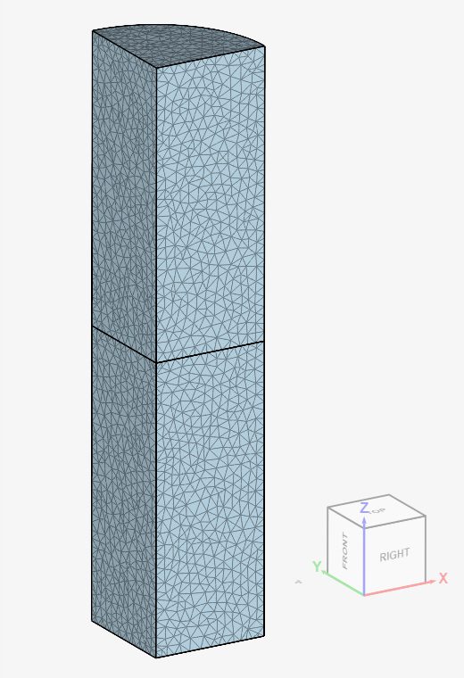
Find below the mesh used for Case D. It is a standard mesh with second-order tetrahedral cells.
Simulation Setup
Material:
- Steel (linear elastic)
- \(E\) = 208 \(GPa\), \(v\) = 0.3
- Therefore, the shear modulus is 80 \(GPa\).
Boundary Conditions:
- Constraints
- Fixed support on face ABC
- Face A’B’C’ is rotated with an angle \((\theta)\) of 2e-4 \(rad\)
- Contacts
- Single part shaft
- Cyclic symmetry: face AA’B’B is tied to face AA’C’C. Rotation axis: z-axis. Sector angle: 90º
- Split shaft
- Cyclic symmetry: face AA”B”B is tied to face AA”C”C. Rotation axis: z-axis. Sector angle: 90º
- Cyclic symmetry: face A”A’B’B” is tied to face A”A’C’C”. Rotation axis: z-axis. Sector angle: 90º
- Bonded contact: both parts are bonded at A”B”C”.
- Single part shaft
Reference Solution
The analytical solution for maximum shear stress \(\tau_{max}\) given below is based on Roark\(^1\).
$$\large{\tau _{max}}=\frac {\theta.G.r}{l} = 3.2 \ [MPa]$$
Result Comparison
The results obtained from SimScale for the maximum shear stress \(\tau_{max}\) at point B’ are compared with the analytical solution by [Roark].
| Case | Quantity | Roark | SimScale | Error (%) |
| (A) | Maximum shear stress \(\tau_{max} [MPa]\) | 3.2 | 3.209 | +0.289 |
| (B) | Maximum shear stress \(\tau_{max} [MPa]\) | 3.2 | 3.191 | -0.279 |
| (C) | Maximum shear stress \(\tau_{max} [MPa]\) | 3.2 | 3.195 | -0.152 |
| (D) | Maximum shear stress \(\tau_{max} [MPa]\) | 3.2 | 3.180 | -0.639 |
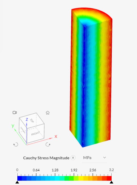
Inspecting the Cauchy stress magnitude for Case B in the post-processor:
References
- W. C. YOUNG, R. G. BUDYNAS. Roark’s Formulas for Stress and Strain. Seventh Edition. McGraw-Hill. 2002. p. 415.
Last updated: November 7th, 2023
Did this article solve your issue?
How can we do better?
We appreciate and value your feedback.


