Documentation
This result control item allows calculating forces and moments in the course of the simulation by integrating the pressure and skin-friction over a boundary. It is possible to select a set of boundaries to calculate the overall force and moment on them.
It can be added under Result Control in the simulation setup tree entry.
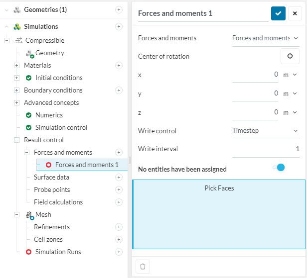
The Center of rotation is commonly defined as the center of mass of the structure. In some simulation projects, it may be convenient to define different coordinates for the center of rotation. For example, if a part is attached to the ground at a specific point, you can use the coordinates of this point to obtain the resulting moments.
Write interval controls how often the force and moment values should be output/written. The value is the number of time steps between the outputs.
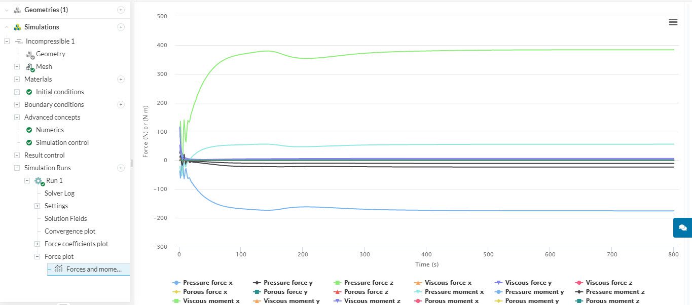
Values of force and moment are printed in the solver log. The plots are updated while the simulation is running. The figure below shows a sample plot of forces and moments:
Alternatively, it is possible to calculate force and moment coefficients instead of force and moment values. In addition to the previous parameters, the user should supply lift, drag, and pitch directions, as well as freestream velocity magnitude, reference area, and reference length. The results are available in the simulation log and as plots.
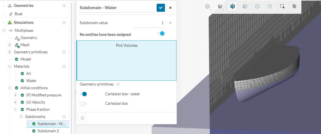
Multiphase flow simulation, as the name suggests, models two fluids of different densities and their interaction with each other in the flow domain. This is done through a phase fraction variable \(\phi\) that takes a value of 0 for one fluid and 1 for the other.
Depending on the case, one might be interested in computing the cumulative force of both or only one of the fluids on the object they interact with. For example, in the simulation of a boat sailing on a water surface represented by the following figure, one could calculate the net drag force on the boat due to both water and air, or only one of them.
Find below the procedure to compute this cumulative force and how to separate forces using the phase fraction.
To post-process your results locally, ParaView should be installed on your computer. Depending on your operating system, the appropriate version of ParaView can be downloaded from here.
Step 1: Download and Open the Results
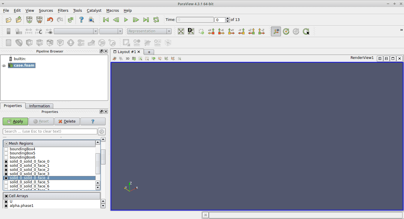
Once a simulation is completed on the SimScale platform, the results can be downloaded to your local system. See Post-processing via a 3rd-party solution for a detailed description of how this can be done. By default, ParaView loads the entire data set. However, the interest now lies only in computing the forces on certain specific faces of the body. Therefore, before opening the case, please make a list of these faces.
ParaView works as a sequence of filters applied to objects in its pipeline.
Step 3: Calculate the Forces
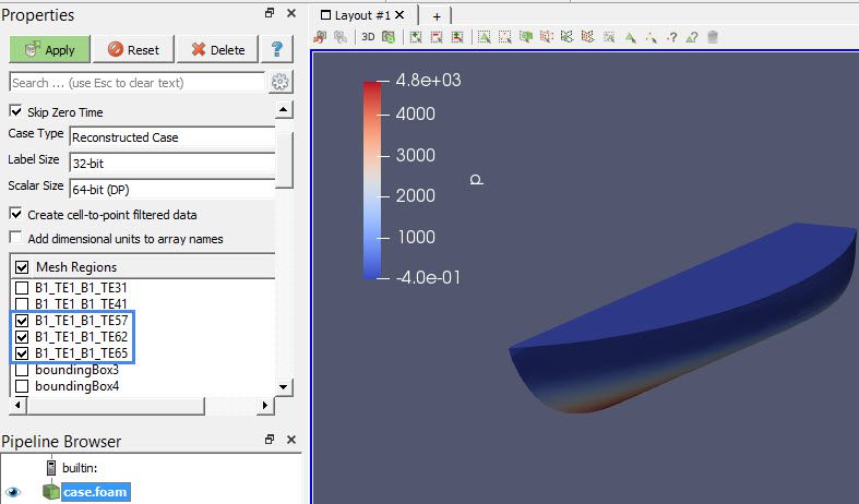
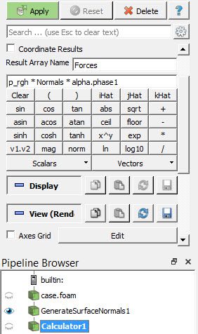
In Step 2, we computed the normals on the faces of interest. These normals are scaled according to the area of the respective faces. Since we already have the pressure data on these faces, we can now easily compute the net force on each face.
For example, in the figure below, we are calculating the forces generated by alpha.phase1 onto the boat:
Note
The reason why density is not required as input is because we already know the static pressure. Therefore, simply multiplying with the area is sufficient to compute the force.
Step 4: Integrate the force over the faces
The result of Step 3 is local to each face. To get the net force on all faces, this result needs to be integrated.
A spreadsheet view opens up. The Forces tab displays the net force value (in Newtons) in the three coordinate directions.
Last updated: May 26th, 2021
We appreciate and value your feedback.
Sign up for SimScale
and start simulating now


