Documentation
Pressure inlet and outlet conditions are typically assigned in computational fluid dynamic analysis (CFD), at the opposite end of the model to a flow rate or a different pressure.
Here are a couple of typical examples of combinations that are used:
In those cases where we know the flow rate conditions, the recommended boundary condition combinations for the inlet and outlet region are the following:
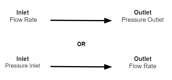
In those cases where we know the pressure conditions, the recommended boundary condition combinations for the inlet and outlet region are the following:

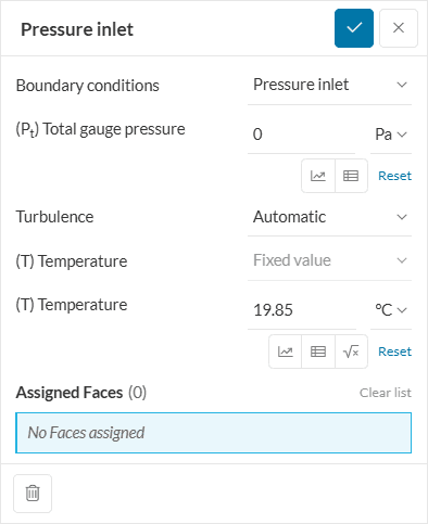
The pressure inlet boundary condition defines an inflow condition based on the known pressure value (P) at the boundary. It is used when no flow rate is known, or if a flow rate (or velocity) is assigned at the outlet.
Important
For compressible analyses, temperature properties are also required at the inlet.
The turbulent flow quantities are matched with the values specified for the Initial Conditions and are thus not required as inputs.
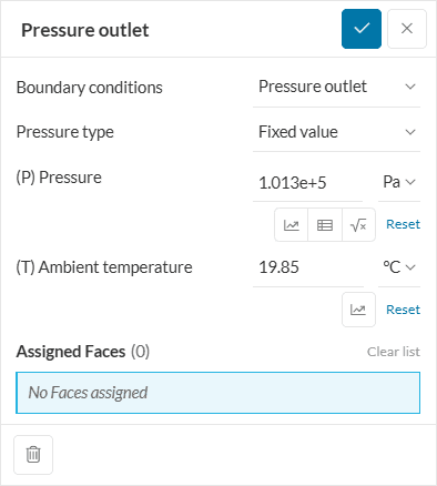
The pressure outlet boundary condition defines an outflow condition based on the flow pressure \(P\) at the outlet. This is usually used when there is a flow rate (or velocity), or a higher pressure assigned at the inlet.
All relevant unknown flow quantities, e.g., temperature in case of compressible flow, and other quantities, including turbulence, are calculated from the interior of the domain with gradients of the quantities fixed to zero value.
The pressure values at the inlet and the outlet can be assigned using the following types:
These four types are described in detail below:
The total pressure expression, defined by velocity vector \((\vec{U})\) and density \(\rho\):
$$ p =p_0 -\ 0.5 \rho\ |\vec{U}|^2 \tag{1}$$
Under certain conditions, the user might need to specify a parameter Gamma \((\gamma)\) which is used in transonic and supersonic cases.
The static pressure \((p)\) is calculated at the boundary based on the fixed total pressure \((p_0)\) that must be specified. The velocity \((U)\) and static pressure \((p)\) are adjusted accordingly until they converge to a stable configuration.
Additionally, the user can also input values in the form of a table by uploading a .csv file or entering the values manually. The following figure highlights the icon that serves this purpose.
Correct dependencies should be chosen. In this case, the uploaded file contains values that are dependent on time only.
Note
When using pressure inlet of type total pressure, it is generally recommended to use pressure outlet boundary condition type.
This prescribes the pressure value on the outlet boundary of the domain. This value could be constant or dependent on time and/or space coordinates. Either gauge or absolute pressure can be used, depending on whether the compressibility is toggled on.
The Fixed value option also allows you to input a table. In this case, the uploaded file contains values that are dependent on time or space coordinates.
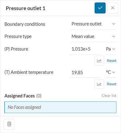
This is only used at an outlet where it is not clear that the flow passes over the boundary uniformly. The average pressure over the boundary would equal this assigned value. Unlike the fixed value, not every region on the boundary needs to have the same value.
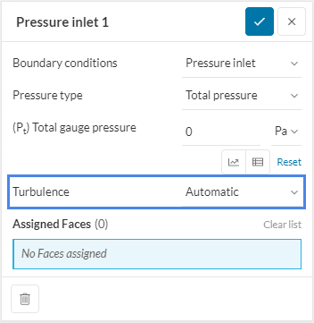
SimScale allows for the definition of turbulence at the velocity inlet. The user has three options to choose from.
The values can either be fixed or driven by a formula or a table for space or time-dependent conditions.
When automatic is assigned a fixed turbulence value of 5 \(%\) is chosen for the turbulent intensity \((I)\). The turbulent mixing length \((L)\) is calculated as 0.07 \((D_{h})\), where \((D_{h})\) is the hydraulic diameter of the boundary face.
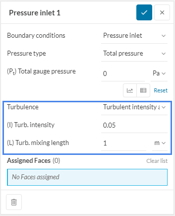
When the Turbulent intensity and mixing length option is selected, the user can specify the turbulent intensity \((I)\) and the turbulent mixing length \((L)\).
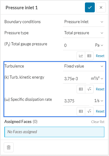
Fixed Value allows the user to directly specify the turbulent kinetic energy in \([\frac{m^2}{s^2}]\) and the specific dissipation rate \([\frac{1}{s}]\).
Available only for compressible flows, the hydrostatic pressure formulation is suitable for atmospheric flows with perfect gas fluids. The pressure decreases with increasing height to keep the domain at hydrostatic equilibrium. The ambient pressure in the input sets the pressure at the ground level.
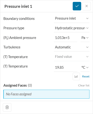
(T) Temperature is the temperature of the fluid at the inlet.
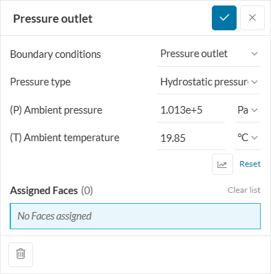
(T)Ambient temperature is the backflow temperature, necessary to define, in case of outlet recirculation, i.e., the temperature at which the fluid would be reentering the domain
Modified pressure, also known as pseudo-dynamic pressure or non-hydrostatic pressure, is used for the initial or boundary condition definition in analysis types that take buoyancy effects into account. The formula below shows the correlation between the modified static pressure \(p_{rgh}\) and the static pressure \(p\):
$$ p_{rgh} = p\ – \rho g h \tag{2} $$
In equation 2, \(\rho\) is the density of the fluid, \(g\) is gravity, and \(h\) is the height of the column of the fluid. Combined, the \(\rho g h\) term represents the hydrostatic pressure.
The following analysis types use modified pressure or modified gauge pressure in the definition of initial conditions and certain boundary conditions:
Modified Pressure Concept
Modified pressure is not a physics concept but a mathematical construct.
This feature enables a hydrostatic pressure profile in the pressure inlet and outlet boundary conditions in Multi-purpose analysis type when the gravity magnitude is non-zero. The following formula shows how hydrostatic pressure \(P_{h}(\vec{x})\) is calculated at each boundary:
$$ P_h(\vec{x}) = P – \rho(\vec{x}) \vec{g} \cdot \left( \vec{x} – \frac{\vec{g}}{|\vec{g}|} h_{\text{ref}} \right) \tag{3} $$
Where \(P\) is the static pressure, \(\vec{g}\) is the gravity vector, \(\vec{x}\) is the position vector and \(h_{ref}\) is the reference height where hydrostatic pressure is equal to the static pressure. Both \(\vec{x}\) and \(h_{ref}\) are with respect to the global coordinate system.
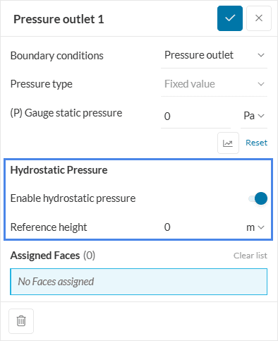
In the user interface, after selecting the pressure inlet or pressure outlet boundary condition, you can enable hydrostatic pressure with a toggle. If activated, you must specify a reference height (\(h_{\text{ref}}\), default 0 \(m\)).
Note
1. Only static pressure can be used when hydrostatic pressure is enabled. If total pressure is defined, a warning will indicate its incompatibility.
2. For transient simulations, the pressure needs to be constant in time. If the pressure is defined as a time-dependent table, a warning will notify the incompatibility.
Users can sweep through different pressure levels using SimScale’s parametric experiment capabilities. To learn more about this capability, make sure to check this article:
Last updated: August 11th, 2025
We appreciate and value your feedback.
Sign up for SimScale
and start simulating now