Validation Case: Free Vibrations on Elastic Support
This validation case belongs to vibrations and the elastic support boundary condition in solid mechanics. The aim of this test case is to validate the following parameters:
- Elastic support
The simulation results of SimScale were compared to the results derived from [Schaum]\(^1\).
Geometry
The geometry used for the case is as follows:
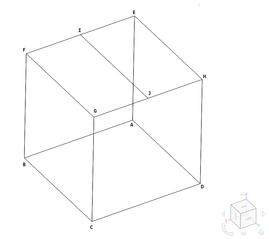
The cube has an edge length of 1 \(m\), with the upper face partitioned in half.
Analysis Type and Mesh
Tool Type: Code Aster
Analysis Type: Static Linear and Dynamic
Cases corresponding to analysis type are as follow:
| Case | Analysis Type |
|---|---|
| A-1 | Static Linear |
| A-2 | Dynamic |
| B-1 | Static Linear |
| B-2 | Static Linear |
| B-3 | Static Linear |
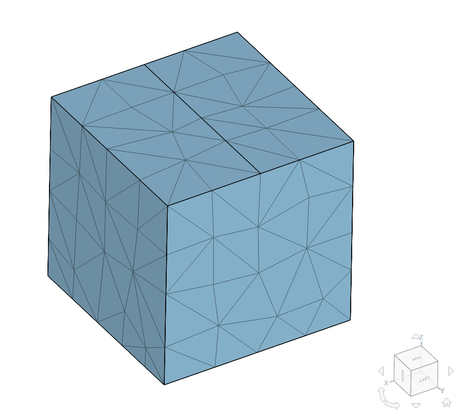
Mesh and Element Types:
Tetrahedral meshes were computed using SimScale’s standard mesh algorithm and manual sizing.
| Case | Mesh Type | Number of Nodes | Number of Elements | Element Type |
|---|---|---|---|---|
| A-1 | 1st Order Tetrahedral | 45 | 97 | Standard |
| A-2 | 1st Order Tetrahedral | 45 | 97 | Standard |
| B-1 | 1st Order Tetrahedral | 128 | 405 | Standard |
| B-2 | 1st Order Tetrahedral | 128 | 405 | Standard |
| B-3 | 1st Order Tetrahedral | 128 | 405 | Standard |
Simulation Setup
Material:
- Linear Elastic Isotropic:
- \( E = \) 205 \(GPa \)
- \( \nu = \) 0.28
- \( \rho = \) 10 \(kg/m^3 \)
Boundary Conditions:
- Constraints:
- Case A-1/A-2:
- Total isotropic spring stiffness \( K = \) 9810 \(N/m\) on face EFGH
- Case B-1:
- Total isotropic spring stiffness \( K = \) 4905 \(N/m\) on face EIGJ
- Total orthotropic spring stiffness \( K_x = K_y = K_z = \) 4905 \(N/m \) on face IFJH
- Case B-2:
- Distributed isotropic stiffness \( K/A = \) 9810 \(N/m^3\) on face EIGJ
- Distributed orthotropic stiffness \( K_x/A = K_y/A = K_z/A = \) 9810 \(N/m^3 \) on face IFJH
- Case B-3:
- Total isotropic spring stiffness \( K = \) 1962 \( N/m \) on face EIGJ
- Total orthotropic spring stiffness \( K_x = K_y = K_z = \) 1962 \( N/m^3 \) on face IFJH
- Distributed isotropic spring stiffness \( K/A = \) 3924 \( N/m^3 \) on face EIGJ
- Distributed orthotropic spring stiffness \( K_x/A = K_y/A = K_z/A = \) 3924 \( N/m^3 \)
- Total isotropic spring stiffness of \( K = \) 1962 \( N/m \) on face EFGH
- Case A-1/A-2:
- Loads:
- Self weight with gravitational acceleration \( g = \) 9.81 \( m/s^2 \) in the \( -Z \) direction.
The following table summarizes the elastic support boundary conditions by case:
| Case | Elastic Support Type on Face EIGJ | Elastic Support Type on Face IFJH | Elastic Support Type on Face EFGH |
|---|---|---|---|
| A-1 | – | – | Isotropic Total |
| A-2 | – | – | Isotropic Total |
| B-1 | Isotropic Total | Orthotropic Total | – |
| B-2 | Isotropic Distributed | Orthotropic Distributed | – |
| B-3 | Isotropic Total+Distributed | Orthotropic Total+Distributed | Isotropic Total |
Reference Solution
The analytical solutions for the rotation angle \(\theta_B\) and maximum shear stress \(\tau_{max}\) are given by the following equations:
Cases A-1, B-1, B-2, B-3:
\( x = \frac{mg}{k} \tag{1} \)
Case A-2:
\( x(t) = V_0 \omega Sin(\omega t) + X_0 Cos(\omega t) \tag{2} \)
\( \omega = \sqrt{ k / m} \tag{3} \)
\( V_0 = -0.01 m/s \)
\( X_0 = -0.02 m \)
\( X_eq = -0.01 m \)
\( 2 <= t <= 4 \)
The computed reference solution is:
\( x_{static} = 0.01\ m \)
\( \omega = 31.32\ Rad/s \)
\( x(t) = (-3.193*10^{-4})Sin(31.32t) – 0.01Cos(31.32t) \tag{4} \)
*\( x(t) \) corresponding to the displacement with respect to the equilibrium position.
Result Comparison
Comparison of displacement DZ on static cases:
| CASE | DZ | REF | ERROR |
|---|---|---|---|
| A-1 | 0.01 | 0.01 | 0 % |
| B-1 | 0.01 | 0.01 | 0 % |
| B-2 | 0.01 | 0.01 | 0 % |
| B-3 | 0.01 | 0.01 | 0 % |
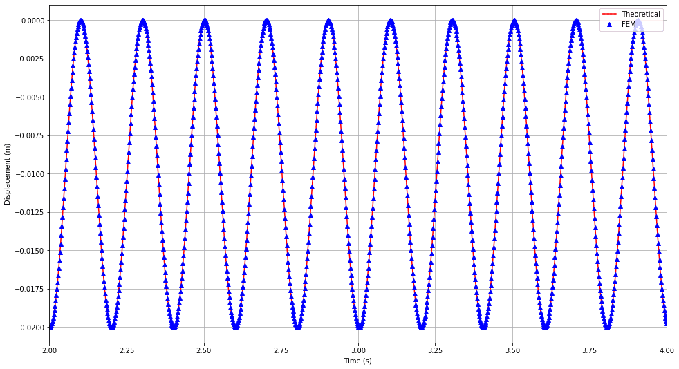
Comparison of transient displacement of face ABCD in dynamic case can be found in Figure 3. Here the vibrations from the elastic support condition can be appreciated.
References
- (2011)”McGraw-Hill Schaum’s outlines, Engineering Mechanics: Dynamics”, pg 271-273, N. W. Nelson, C. L. Best, W. J. McLean, Merle C. Potter
Note
If you still encounter problems validating you simulation, then please post the issue on our forum or contact us.
Last updated: April 21st, 2026
Did this article solve your issue?
How can we do better?
We appreciate and value your feedback.


