In this article, we will explore the effect of the number of mesh elements and nodes across thin wall parts on the results of heat transfer simulations. Then, we will show some Workbench tips on how to obtain good quality meshes for this particular scenario.
Illustrative Example
Let’s consider the case of a corner wall, subject to heat transfer from the inside to the outside faces. The geometry is meshed with three different scenarios:
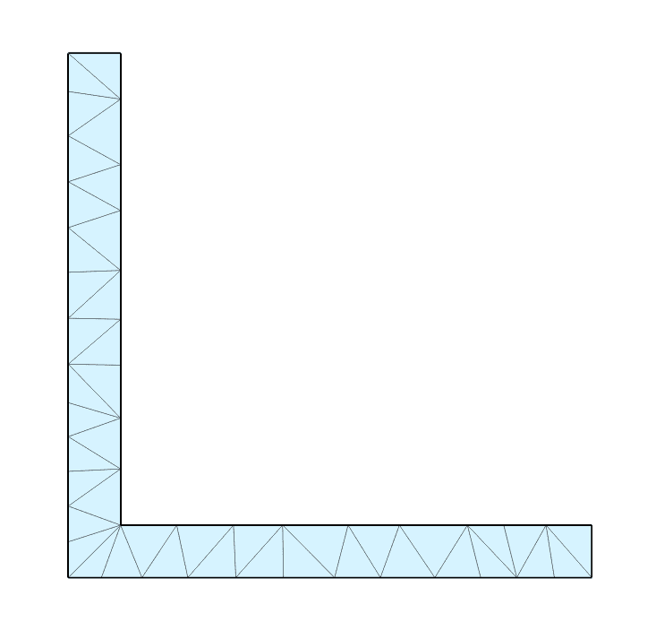
- First order mesh, one element across the thickness
- First order mesh, two elements across the thickness
- Second order mesh, one element across the thickness
The geometry and meshes are illustrated below:
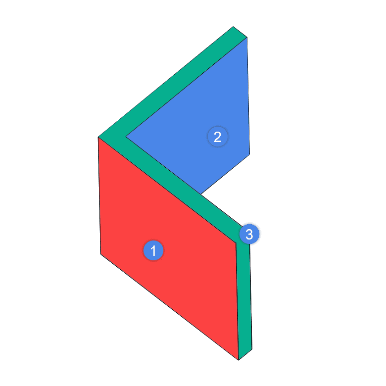

The thin wall is subject to a 100 \(°C\) temperature difference from the internal surface (2) to the external surface (1), with the adiabatic condition at the wall cut faces (3). The resulting temperature contours for each model are shown below:
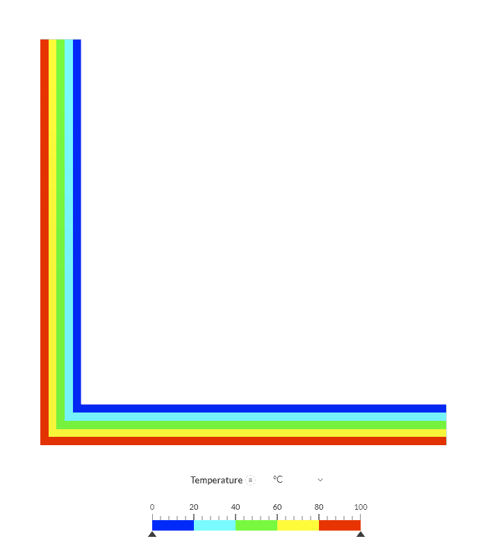
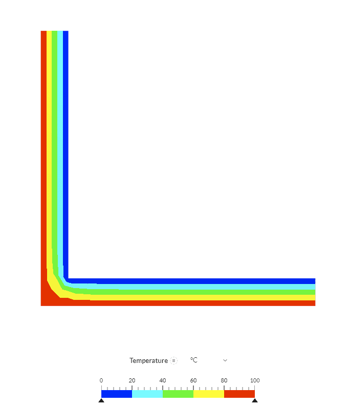
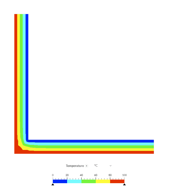
There are a few aspects to take into account here. The first one is that the color gradient you see is created by the post-processor because all the FEA results are currently written only on the mesh nodes. This is why we are able to create the 5-step gradient you see in figures 5 to 7.
Now, on the wall edges where the adiabatic conditions are applied, we can see that results across all the meshes are the same. Basically, just a linear gradient between inner and outer temperatures. This indicates that the gradient is actually linear because the results from meshes 2 and 3 coincide with the interpolation of the post-processor.
The region of interest is the corner, where we can actually see a difference between the models: Mesh 1 shows a linear gradient from the inner to the outer surfaces at the corner location, which is created by the post-processor interpolation. On the contrary, for meshes 2 and 3, the gradient is not linear! We can see that the higher temperature value from the outer corner extends deeper than the lower temperature in the inner region.
Also, we find that the regions with equal temperature, shown in the same color, form a curved path around the corner. This effect is not captured in mesh 1, which does not have nodes inside the wall! This non-linear temperature gradient is caused by the structural discontinuity that the corner creates.
Possible sources of non-linear gradients are structural discontinuities and certain types of boundary conditions. To always be on the safe side, we recommend meshing thin-walled parts with nodes inside the thickness. More nodes across the thickness should be added to capture gradients when needed.
Workbench Implementation
Now that we have made our case on the need for meshes with more than two nodes across the thickness of thin-walled parts, let’s see how this can be implemented in the SimScale Workbench. Let’s check in depth how to achieve the two options showcased in our example application: 2nd order mesh and 1st order mesh with nodes inside the wall.
Option 1: 2nd Order Mesh for Thin Wall
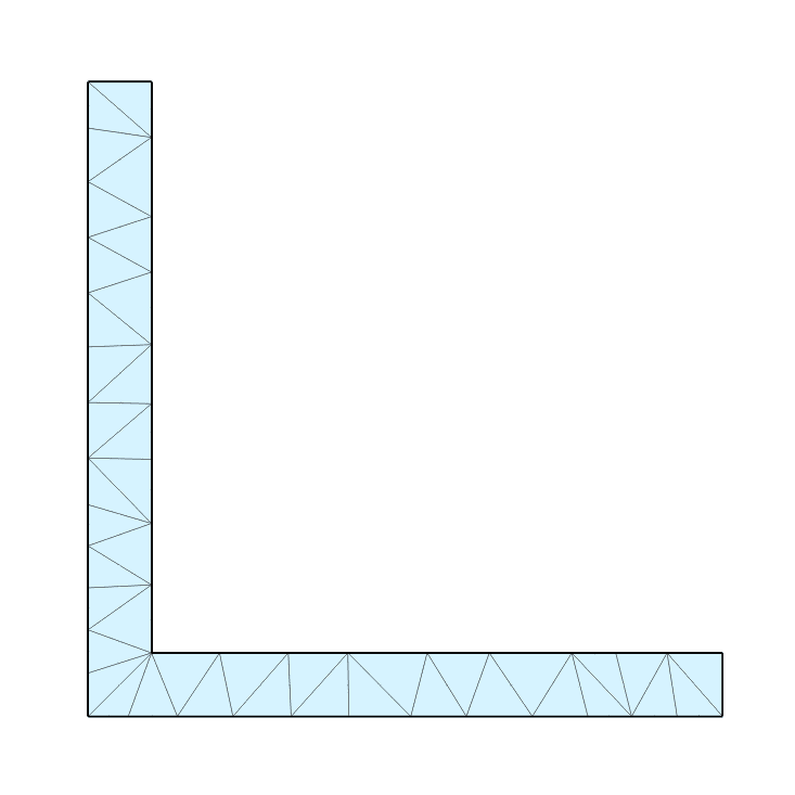
For the 2nd order mesh, we can specify a target sizing that achieves one element across the thickness. Then, a middle node is automatically added when creating the 2nd order elements. The Workbench setup looks as shown:
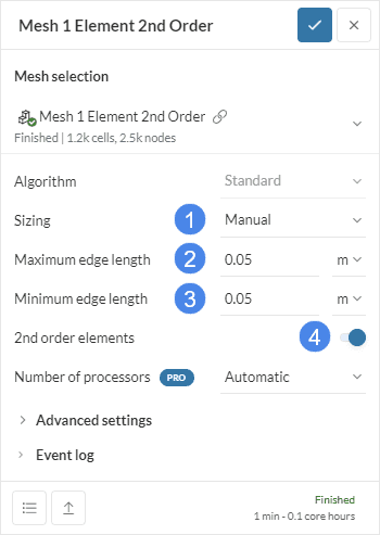
The relevant parameters are:
- Sizing is set to Manual
- Maximum edge length is set higher than the wall thickness (0.01 \(m\) in this case)
- Minimum edge length is set equal to the maximum, to achieve the best aspect ratio
- 2nd order elements are toggled on
The result is the mesh shown in Figure 4 above.
Option 2: 1st Order Mesh for Thin Wall
For the 1st order mesh, we must specify a target sizing that achieves two elements across the thickness. This will ensure that we will have the needed node inside the wall. The workbench setup is as follows:
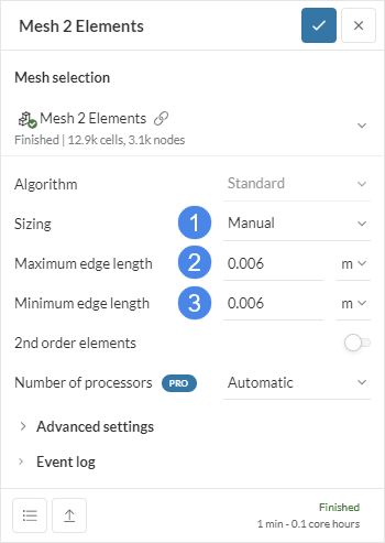
The relevant parameters are:
- Sizing is set to Manual
- Maximum edge length is set to around half of the wall thickness
- Minimum edge length is set equal to the maximum, to achieve the best aspect ratio
Please see Figure 3 above for the resulting mesh.


