You might have landed on this article because you saw the warning shown below and are now wondering what the term “interpolated data” means in the context of SimScale post-processing.
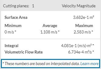
For those of you who only want to know how to switch between the interpolated (node) and non-interpolated (cell) view mode, see the note below:
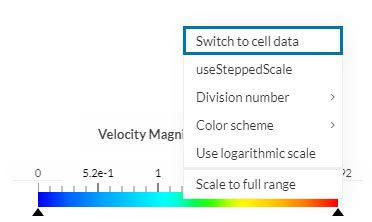
How to switch between cell and node data?
Right click on the legend bar in the bottom of the screen to find the option to ‘Switch to cell data’ and vice versa in the legend bar context menu.
Interpolated Data? Node vs. Cell? What does this mean?
In order to answer these questions, we first need to understand what a mesh is. In essence, getting to a simulation result requires finding a solution the mathematical representation of a physical problem that involves Partial Differential Equations (PDEs). The simulation solvers in SimScale solve these equations based on certain numerical methods. One must note that these are complex problems, which are a lot easier to solve for a small section than for the entire simulation domain at once.
Therefore, before handing over the simulation problem to those solvers, we first need to split the simulation domain into many small pieces called cells. And all mesh cells together form a so called mesh.
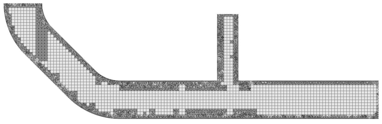
Now, in order to generate a good mesh, we have to make a tradeoff. If we make the individual cells too large, the overall problem complexity and solve time reduces, but we might run the risk of getting a physically non-accurate result. On the other hand, if the mesh becomes too fine, the accuracy becomes reliable but at the cost of increased computational expenses.
To learn more about meshes, visit our SimWiki article.
The solution we get back, in the end, is stable across the volume of a single cell. Imagine a digital image for example. Each pixel in an image can be compared to a cell in our case. If the pixel is too large, the image looks pixelated. If the pixels are very small, the eye might not be able to distinguish the difference between two high-resolution images anymore.
While not a big problem with images usually, too high of a cell resolution in numerical simulation often leads to unnecessarily long and expensive solve times without leading to a more accurate result.
See below the original cell-based solution field for the flow problem shown above that was computed on the basis of a reasonably sized mesh.
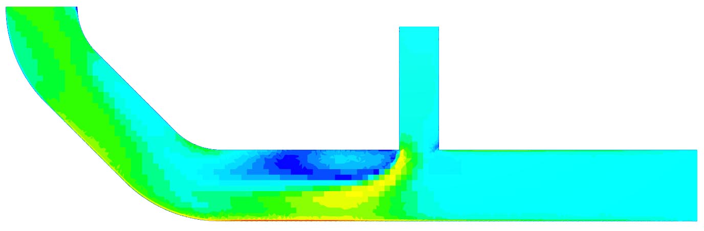
You can easily spot the individual cells in that solution. Now, flow problems in nature don’t behave in such a discrete way. This is where interpolation comes in.
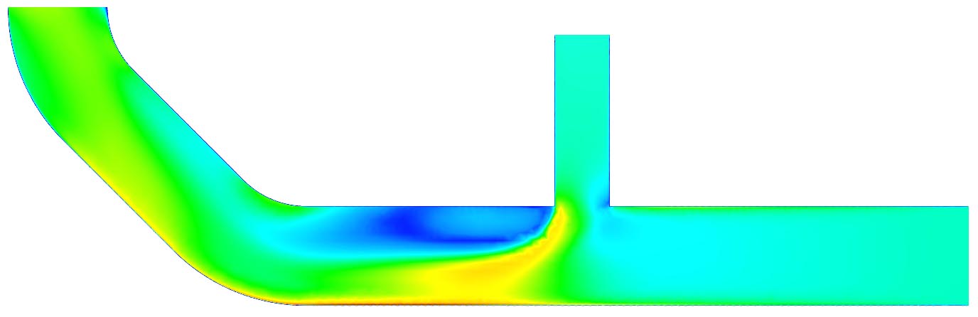
Depending on your use case you might not be interested in this raw, cell-based solution. That’s why most post-processing tools, SimScale included, provide an option to interpolate results. The interpolation algorithm thereby produces a continuous solution between the cell centers (aka. node data) based on the raw discrete solver output.
Which Is Better? Cell or Node Data?
While the interpolated view is visually closer to the behavior (here the flow field) you’d find in nature and thereby lends itself more for visual exploration and taking screenshots or recording animations, note that only the cell-based data view shows the original data. This can make a difference especially when trying to extract quantitative results (e.g. the average flow rate through a plane). In that case it’s advisable to use the original cell data as source instead of the interpolated node data solution.
Conclusion
The choice between the cell and node data depends on what you need. Just be aware that in both cases you’re looking at an approximation of the physical properties of the true behavior you’d see in nature. In the end it’s up to you to make a judgement call which view is closer to reality for the question you’re trying to answer.
Surface vs. volume data
Note that during post-processing, SimScale often provides both volume data (data valid for the volumes of all mesh cells) as well as surface data. In a situation where the data observed is for the inside, the interface and the surface of the domain, the surface data is only available in the node data view. A cell data won’t show what’s happening on the surface or the interface. While the node data view shows interpolated data for the inside of your domain, the surface data is the actual data and does not require interpolation.


