This article sheds light on dos and don’ts recommended when performing a CFD simulation using SimScale’s Multi-purpose solver. The working of the meshing algorithm applied in the Multi-purpose analysis type is here and the user is encouraged to go through it as well.
The Multi-purpose solver employs a binary tree mesher, which generates Cartesian cells that are highly orthogonal and adaptively conform to solid boundaries. The meshing algorithm is automated and follows a top-down approach The bounding box (an imaginary box encompassing the dimensions of the flow domain) is refined anisotropically by cutting cells in the first layer (x-direction), in the second layer (y-direction), and the third layer (z-direction).
For ease of use, SimScale UI provides two options to create the mesh – Automatic Mesher and Manual Mesher. For the majority of internal and external CFD problems, the automatic mesher works really well, where the user only needs to set the refinement level. In case of complex CAD geometries or when the automatic mesher does not yield the desirable mesh, users should switch to the manual mesher, which allows more granular control over the mesh through three simple parameters. Both these methods and scenarios where they should be used are described below.
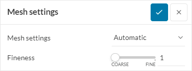
Automatic Mesher
The Automatic Mesher allows users to mesh the whole domain using a simple slider. Behind the scenes, each level in the automatic mesher corresponds to the three parameters viz. Maximum cell size, Minimum cell size, and Cell size on surface. By simply moving the slider, the user can arrive at a mesh configuration that will automatically set the correct mesh parameters.
Automatic Mesher Best Practices
For any new problem, the following workflow is recommended:
- Start with the lowest automesh level i.e. 1. If you are able to generate a viable mesh, then please inspect the mesh for fineness and quality before refining it further.
- You can also add a volumetric refinement zone to specifically refine certain areas of the domain. This is done by using geometry primitives.
- If the automesh level 1 does not work or gives a very coarse mesh, you can increase the slider refinement to higher levels, going up to 10.
- Best practices dictate that you first try to generate a viable mesh by going up to refinement levels 4 or 5. Levels higher than 5 are useful to do a mesh refinement study on an already generated viable mesh. Note that because the automatic mesher levels are relative, going really fine on the slider can increase the mesh cell count exponentially, which in turn can blow up the simulation size. Whether or not such high refinement is needed is subjective and case-dependent. But it is worth being aware of the total mesh count when doing a mesh study.
- If you encounter errors such as “mesh could not resolve small features” or you are not happy with the cell distribution, then there are two options you can try:
- Cleaning up your CAD to remove unwanted features
- Manual Mesher
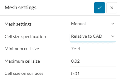
Manual Mesher
To access the Manual Mesher, please change the Mesh settings input from Automatic → Manual. The Manual mesher allows the user to explicitly set the following mesh parameters:
- Maximum cell size
- Minimum cell size
- Cell size on surface
The UI has help text stating the allowable range for each of these parameters. Here, we will look at some best practices to start and iterate upon a manually generated mesh.
Manual Mesher Best Practices
- For internal and most external flow problems, it is recommended to keep the Cell size specification as Relative to CAD. This is the default option and generates mesh relative to the maximum dimension of all CAD surfaces. When this option is ON, all mesh parameters are dimensionless as they are relative to particular CAD geometry.
- Setting the Minimum cell size:
- This is the global setting for the minimum size of mesh cells and is relative to the diagonal of the CAD geometries present in the simulation.
- For most cases, the default value of 7E-04 works fine and need not be changed.
- Setting the Maximum cell size:
- This is the global mesh setting that governs the maximum cell size across the domain. It is relative to the diagonal of all CAD geometries present in the simulation.
- For the first mesh try keeping the maximum cell size as coarse as possible. It is a good practice to start from the default value of 0.02 and generate the mesh.
- Setting the Cell size on surface:
- This parameter governs the mesh distribution on CAD surfaces. By definition, it is relative to the diagonal.
- Cell size on surface is always equal to one half (general usage) or one quarter (for more complex boundaries, e.g. blades in a turbo-machinery case) of the Maximum cell size. The default value already follows this thumb rule.
- Refining the mesh:
- As described above, it is recommended to start with the default values of all the manual mesh parameters. But if this does not yield the desired fineness across features of interest or some features are not resolved at all, then a good practice is to divide both the Maximum cell size and Cell size on surface by two while keeping the Minimum cell size the same.
- For Minimum cell size, a good practice is to leave it at the default value of 0.0007. Only refine this parameter when desired fineness across small features is not achieved. In such a case, inspect your CAD visually and decide about the size of the features that need to be resolved (gaps, passages, channels, blade tips, etc.). The Minimum cell size should be set in such a way that at least 3-4 cells across the feature of interest are guaranteed. Care must be taken when refining this parameter as the mesh size can become too large by refining this parameter to a very small value.
CAD Requirements
In addition to resolving the generic CAD faults we recommend the following:
- Reduce the number of tessellations on the CAD surface i.e. combine small facets together to have a lesser number of surface facets.
- Really thin, elongated faces on the CAD surfaces should be broken up into manageable facets such that the skewness is not too large.


