Documentation
The aim of this validation is to compare the simulation results from SimScale using the Multicomponent feature in its proprietary solver, Multi-purpose, with the experimental results in the study done by Schefer titled “Data Base for a Turbulent, Nonpremixed, Nonreacting Propane-Jet Flow“.
The objective is to understand the flow patterns and concentration distribution of the propane jet in the presence of co-flowing air. The geometry considered is a simple pipe to benchmark the evolution of the propane jet. This type of analysis is useful in the design process of combustion chambers to analyze the gas flame or even the gas injection.
The model consists of a small extended pipe for fuel injection and flow development, and a pipe with a larger diameter where a mixture of gases has to be modeled.

The dimensions of the pipe can be seen in the table below:
| Dimension | Value \([m]\) |
| Jet pipe length | 0.29 |
| Pipe length | 2 |
| Jet pipe diameter (D) | 0.0052 |
| Pipe diameter (D) | 0.30 |
Analysis Type: Steady-state, Multi-purpose with the Multicomponent model and K-Epsilon turbulence model
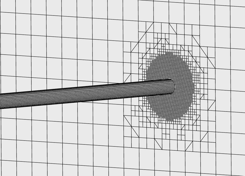
Mesh and Element Types: The mesh is a Cartesian hexahedral mesh, created using SimScale’s Multi-purpose solver.
The Multi-purpose meshing algorithm, utilizing hexahedral cells, was employed to generate the mesh for this simulation. A refinement level of 5 was selected, and two region refinements were implemented: one to enhance the mesh quality near the jet flow region (Target cell size: 0.0008 \(m\)) and another in the main pipe ((Target cell size: 0.01 \(m\)).
| Mesh Type | Number of cells | Element Type |
| Automatic Level 5 | 5095357 | 3D Hexahedral |

The pipe consists of a mixture of Propane, Oxygen, and Nitrogen gases. Each of these gases is treated as a separate ‘component’, with the carrier fluid being air. The physical properties of the different gases as well as other simulation parameters are listed below.
Fluid:
Boundary Conditions:
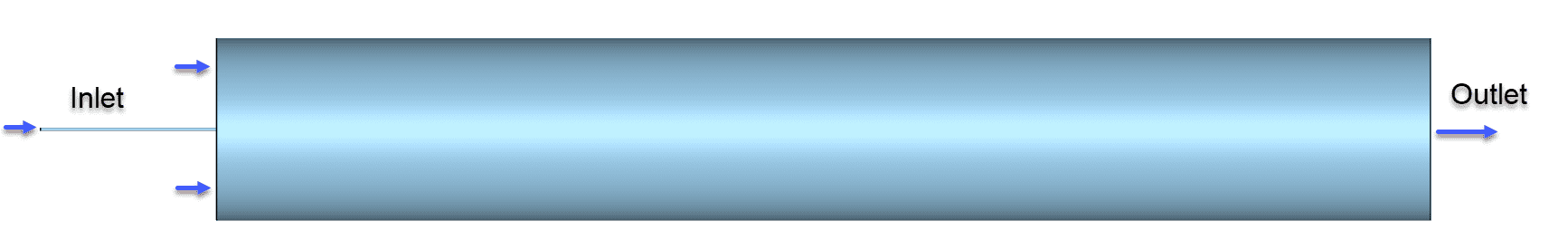
The model’s boundary conditions are different for each region of the domain. The smaller tube represents the region where the propane jet enters, and the larger tube represents the region where air enters, including oxygen and nitrogen as components. As the simulation is compressible, the temperature values were kept constant at 295 \(K\) for the boundary conditions. An ambient pressure was set for the outlet region, and a backflow fraction corresponding to the composition of the air was set, which means that in the case of a backflow, only air is allowed to flow back into the domain.
| Boundary Condition | Value | Mass Fraction (O2) | Mass Fraction (N2) | Mass Fraction (C3H8) | Temperature \([K]\) |
| Velocity inlet (Jet Flow) | 54 \(m/s\) | 0 | 0 | 1 | 295 |
| Velocity inlet (Air) | 9.2 \(m/s\) | 0.23 | 0.77 | 0 | 295 |
| Pressure outlet | 101325 \(Pa\) | 0.23 | 0.77 | 0 | 295 |
| No-slip pipe walls | – | – | – | – | 295 |
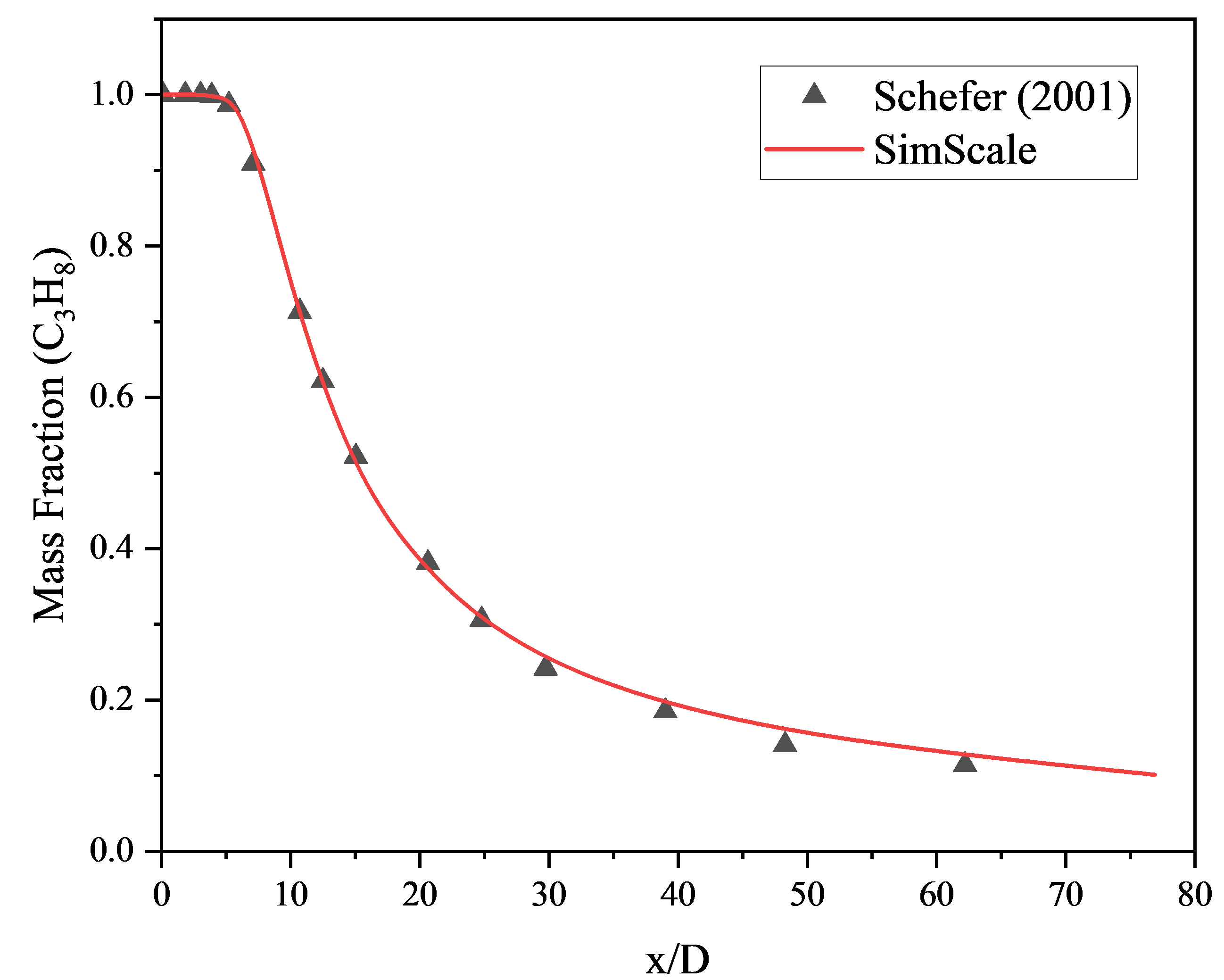
A comparison of the propane jet flow obtained from SimScale against the reference results1 is given below. On the lower axis, the plot shows the relationship between the coordinates of the pipe from the entry of the jet into the larger tube \((x)\), normalized by the jet tube diameter \((D)\). SimScale results for the mass fraction of propane as a function of the pipe coordinate show an excellent correlation with the experimental data.
Axial and radial velocities were also analyzed to assess the profiles and compare the results obtained from SimScale. In this regard, figures 6, 7, and 8 demonstrate that the software effectively represents the physical phenomenon, particularly when examining velocity patterns, although the maximum axial velocity for this case is slightly lower, with an error margin of approximately 4%.
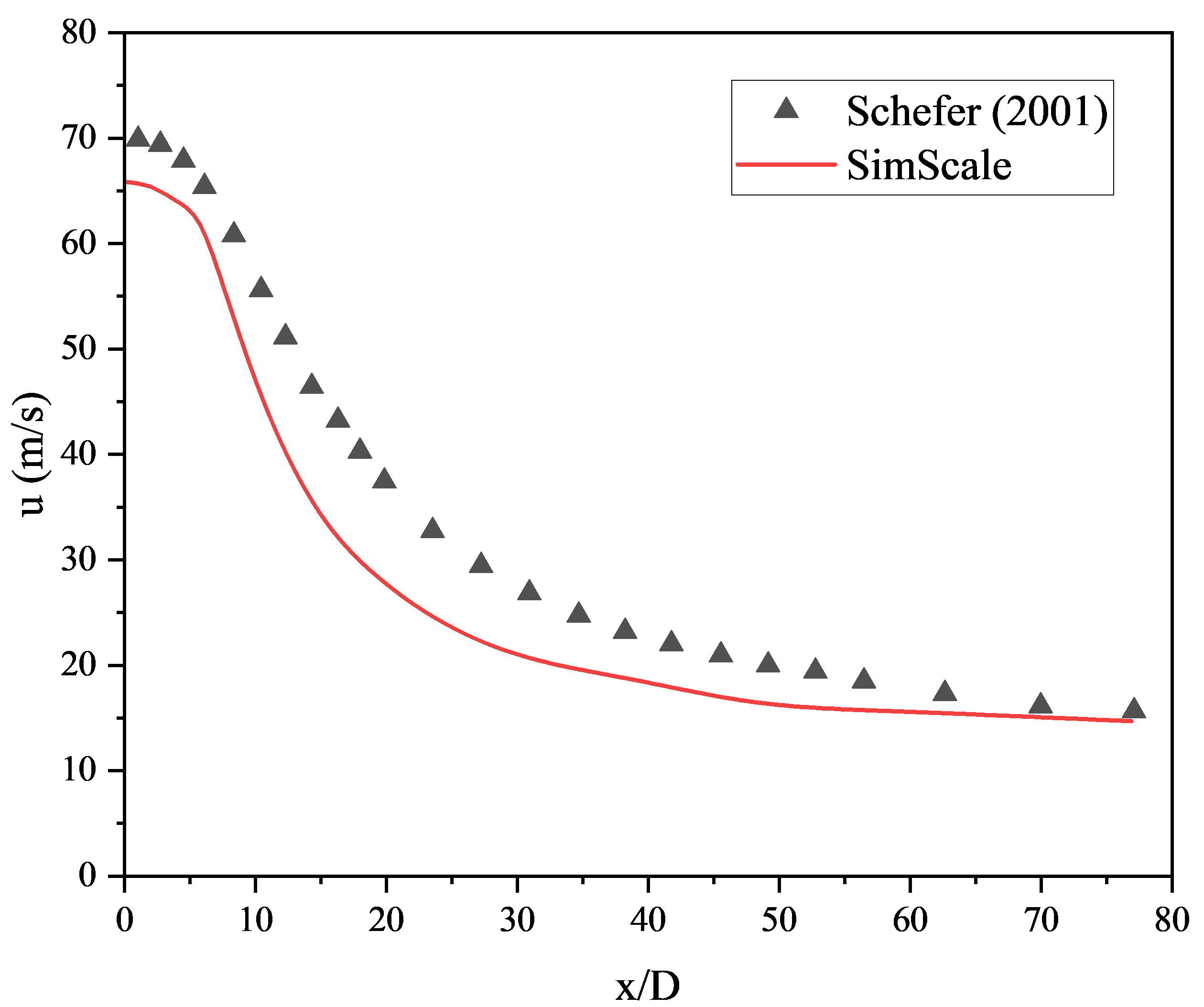
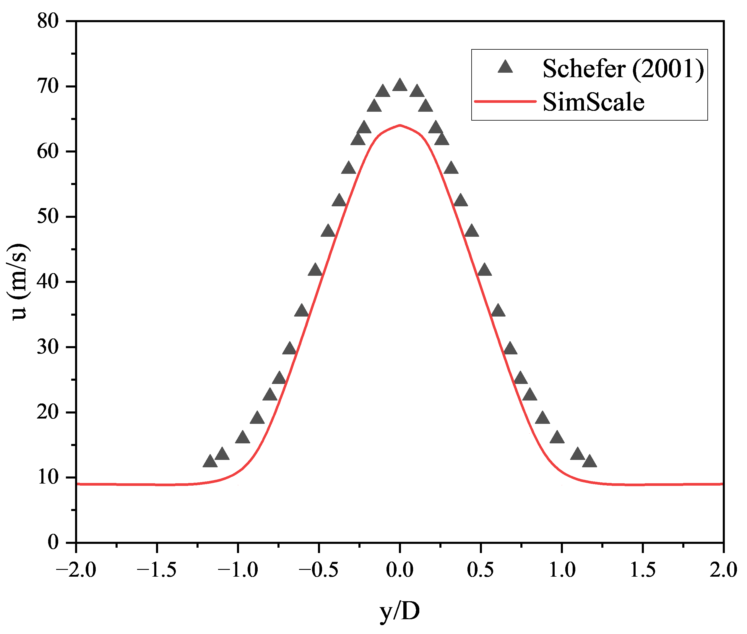
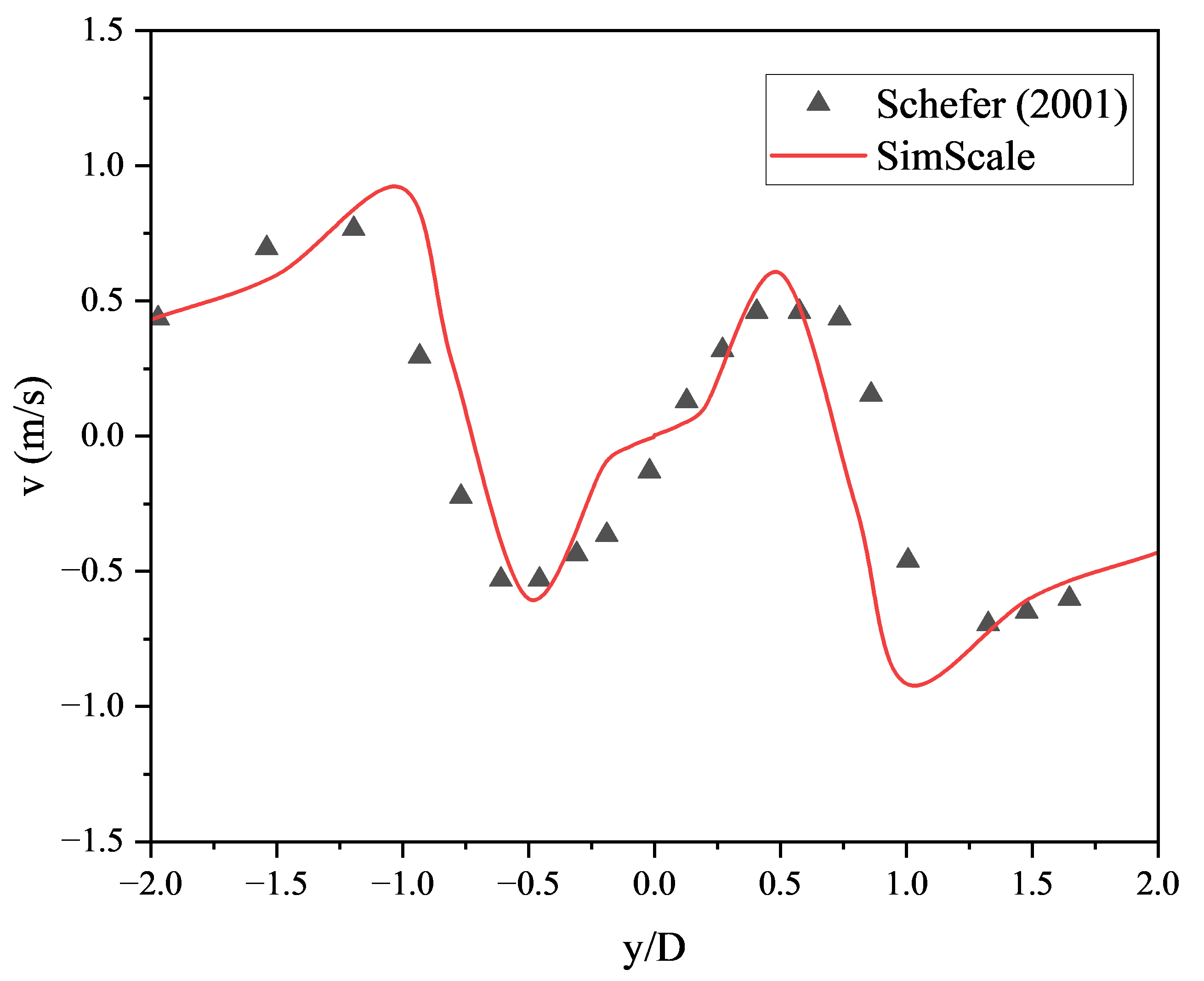
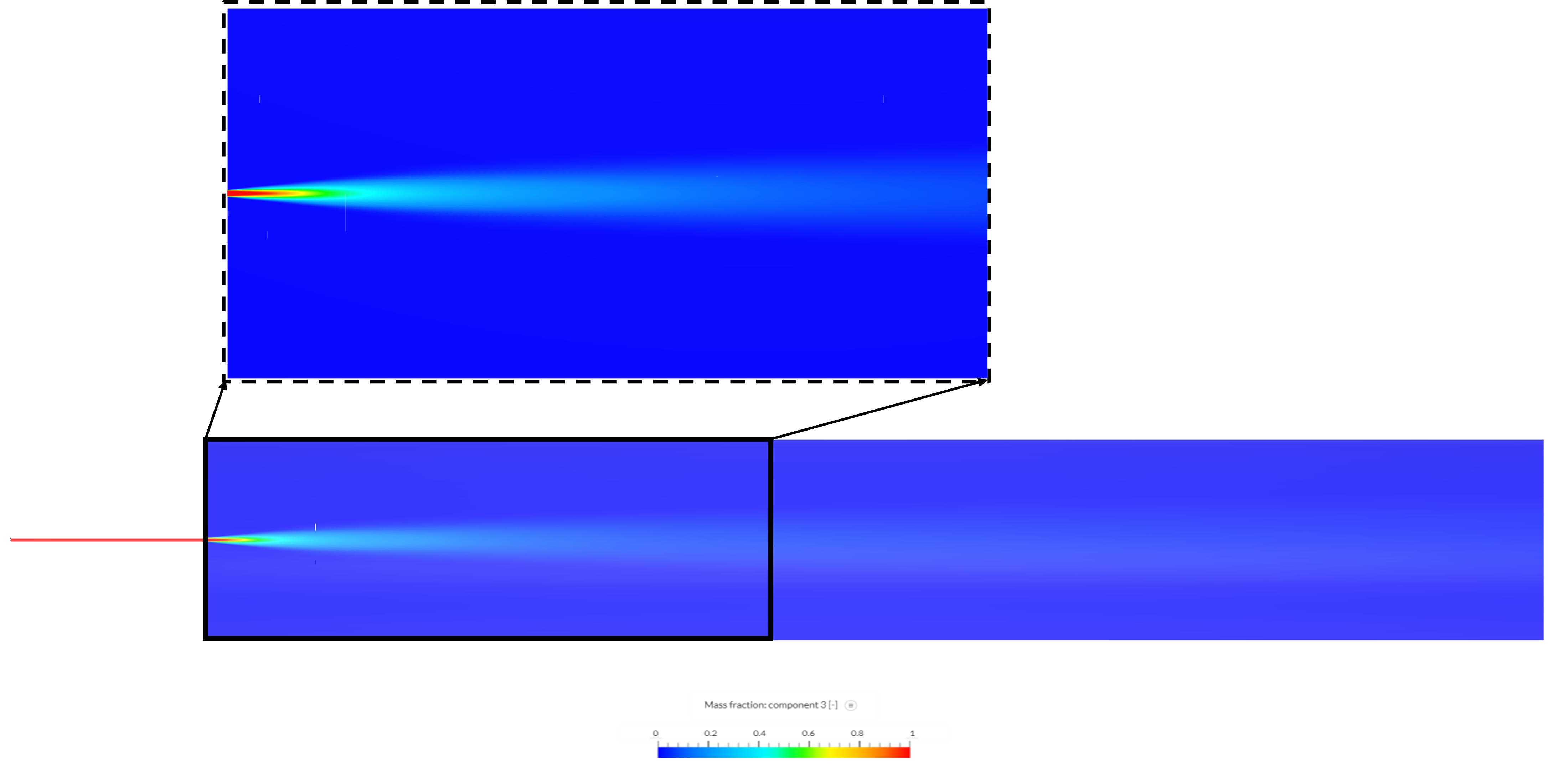
Figure 9 illustrates the jet contour observed in SimScale’s online integrated post-processor, where the analyzed variable represents the mass fraction of propane entering the tube. It shows the mass fraction of propane and its dissipation with the mixture of nitrogen and oxygen gas.
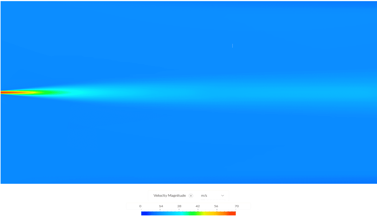
The jet’s flow development aligns with the expected velocity profile, with Figure 10 showing a pronounced velocity gradient at the jet’s center.
References
Note
If you still encounter problems validating you simulation, then please post the issue on our forum or contact us.
Last updated: December 4th, 2024
We appreciate and value your feedback.
Sign up for SimScale
and start simulating now