Documentation
The aim of this validation is to compare the natural convection around cylinder simulation results performed in SimScale using the compressible flow feature in its proprietary solver, Multi-purpose, with the results obtained analytically\(^1\).
This simulation aims at validating the heat loss characteristics from a constant heat flux horizontal cylinder. First, the convective heat transfer coefficient, as well as the corresponding cylindrical surface temperature, is calculated analytically through an iterative approach. After that, the surface temperature values per various surface heat flux values are calculated in the SimScale platform. Finally, the results from the analytical method and the platform are compared.
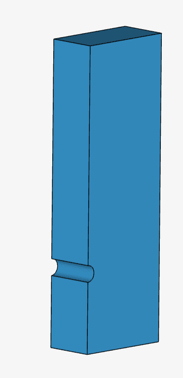
Analytically, the geometry is nothing but a cylinder in a flow domain. For simulation purposes, reducing the computational requirement, we model only 50% of the cylinder-flow domain.
To be able to capture the flow physics, we need to ensure that the domain is large enough. In other words, flow domain boundaries need to be far enough from the cylinder. How far? This needs to be found by testing different flow domain sizes. Slightly increase the domain size until the results no longer change significantly (domain independence test).
The schematic of the cylinder and the flow domain around it is depicted in Figure 1:
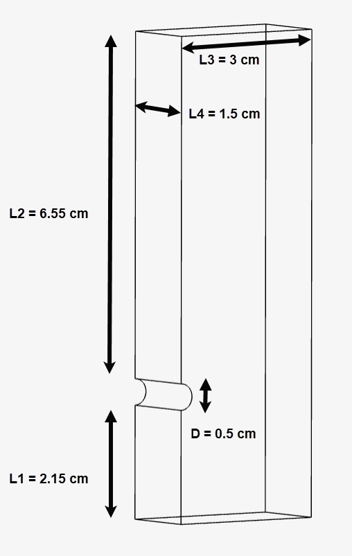
The half-cylinder is 0.5 \(cm\) in diameter, placed 2.15 \(cm\) from the inlet and 6.55 \(cm\) from the outlet. The fluid domain is 1.5 \(cm\) thick and 3 \(cm\) wide. The exact model in SimScale can be observed as follows:
Analysis Type: Steady-state, Multi-purpose with k-epsilon and Compressible model
Mesh and Element Types:
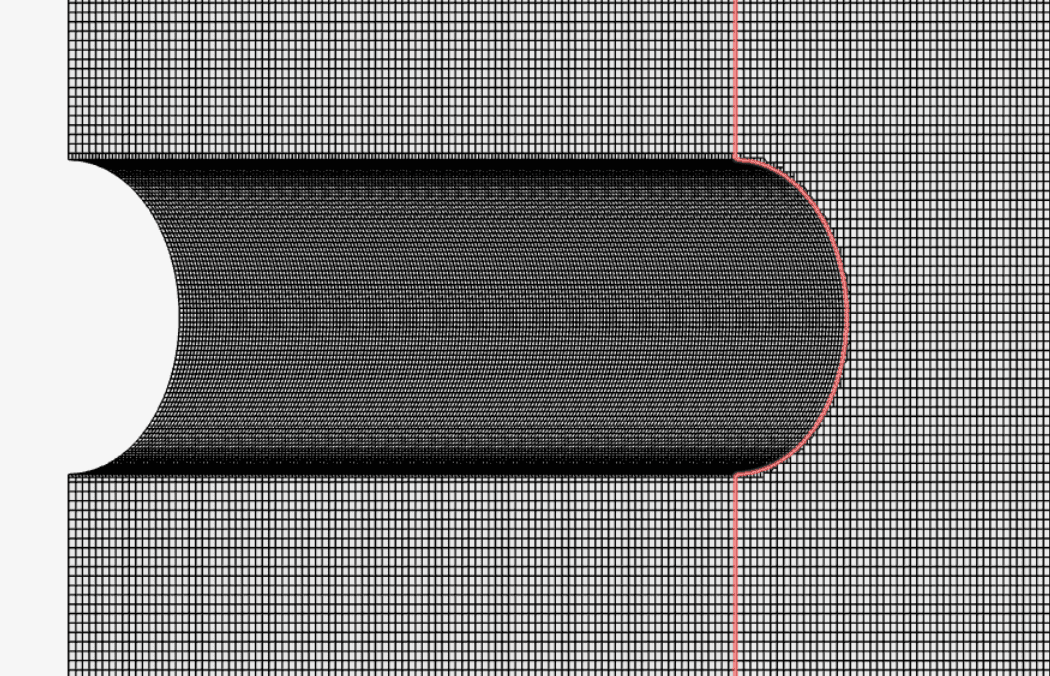
Two meshes were created, Mesh 1 and Mesh 2 — Mesh 2 more refined than the other — to perform the mesh independence study. Both meshes were created with SimScale’s Multi-purpose mesh type, which is a body-fitted structured mesh. An automatic sizing definition was defined with an additional surface refinement at the inlet and the cylinder surfaces.
| Mesh | Mesh Type | Global Fineness | Target Cell Size (refinement) \([m]\) | Number of Cells | Element Type |
| Mesh 1 | Automatic with surface refinements | 8 | 1e-4 | 888702 | 3D Hexahedral |
| Mesh 2 | Automatic with surface refinements | 10 | 1e-4 | 1600369 | 3D Hexahedral |
The resulting Mesh 1 is as observed below. Due to extreme fineness only the part near the cylinder is shown.
Fluid:
Figure 4 shows the schematic of the boundary conditions applied:
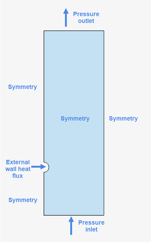
The inlet is set at atmospheric pressure while the outlet at equivalent hydrostatic pressure due to the influence of gravity. The cylinder is assigned a fixed heat flux value while the remaining faces act as a symmetry.
This convective heat transfer validation case is tested for five different values of heat flux. All the values for the boundary conditions are listed in Table 2:
| Boundary Condition | Value |
| Pressure inlet \([Pa]\) | 101325 (Absolute total pressure with 295 \(K\) total temperature) |
| Pressure outlet \([Pa]\) | 100424.28 (Hydrostatic absolute static pressure) |
| External wall heat flux \([W/m^2]\) | 147634.916 107456.01 70228.18 36856.23 9314.75 |
| Symmetry | All other faces |
The following section explains the calculation for the analytical results using equations as stated in [1].
Natural convection heat transfer is calculated as follows:
$$ q = \alpha (T_s – T_{amb}) \tag{1}$$
Where
Convection coefficient \(\alpha\) is a function of the material properties and the geometry.
$$ \alpha = Nu \frac{k}{L} \tag{2}$$
Where
Calculation of the Nusselt number requires an empirical correlation. Natural convection from a horizontal heated cylinder (constant heat flux) is calculated by using the following empirical equation:
To be able to calculate the surface temperature \((T_s)\), we need to know the convection coefficient \((\alpha)\). \(\alpha\) is a temperature-dependent characteristic. This means the calculation of surface temperature is an iterative process.
The values for heat flux, convection coefficient, and surface temperature are listed in Table 3 below.
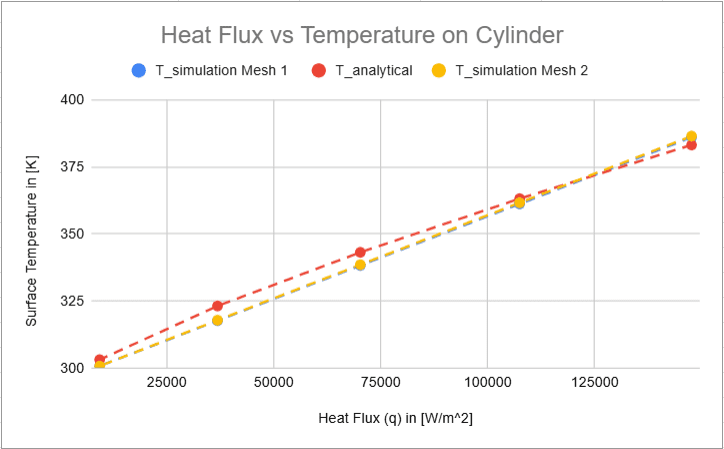
An average surface temperature over the cylinder surface was calculated per value of the heat flux (see Table 2) for both meshes, Mesh 1 and Mesh 2. The difference between the values evaluated with each mesh is negligible.
The result output from the SimScale simulation is compared against the analytically obtained surface temperature values.
| \(q\) \([W/m^2]\) | \(\alpha\) \([W/m^2.K]\) | \(T_{analytical}\) \([K]\) | \(T_{simulation}\) \([K]\) Mesh 1 | \(T_{simulation}\) \([K]\) Mesh 2 | Error %, \(T_{simulation}\) Mesh 1 and \(T_{analytical}\) |
| 147634.916 | 1.64E+03 | 383.15 | 386.02 | 386.45 | 0.749 |
| 107456.01 | 1.53E+03 | 363.15 | 361.19 | 361.61 | -0.539 |
| 70228.18 | 1.40E+03 | 343.15 | 338.26 | 338.53 | -1.425 |
| 36856.23 | 1.22E+03 | 323.15 | 317.7 | 317.85 | -1.686 |
| 9314.75 | 9.18E+02 | 303.15 | 300.74 | 300.77 | -0.795 |
SimScale results show a very good agreement with analytical ones. The calculated deviation is less than 2%.
Here onwards, visual results for only Mesh 1 study are shown:
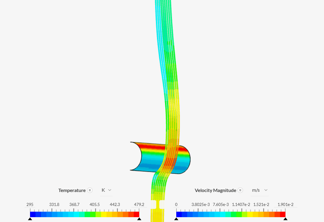
The cylinder surface temperature increases as we travel away from the inlet. This happens because the oncoming cold water temperature increases as it travels upwards after coming in contact with the cylinder.
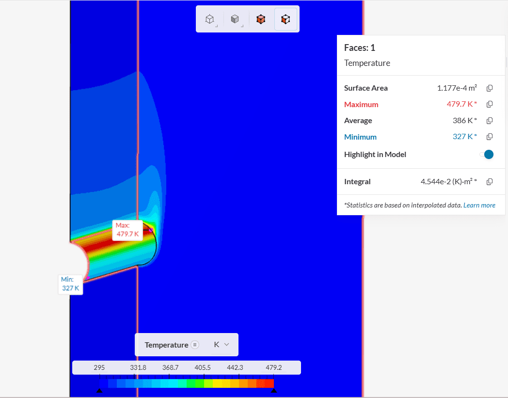
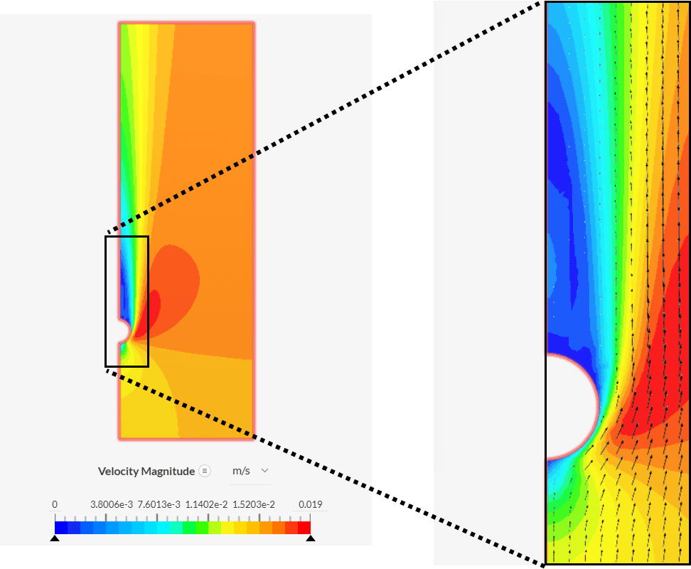
On close observation using the vectors we observe a flow circulation above the cylinder. The reverse water flow helps to reduce the temperature of the cylinder surface closer to the symmetry face.
This also explains why the maximum point of temperature on the cylinder surface is not the farthest from the inlet (see Figure 7).
References
Note
If you still encounter problems validating your simulation, then please post the issue on our forum or contact us.
Last updated: June 23rd, 2025
We appreciate and value your feedback.
Sign up for SimScale
and start simulating now