Documentation
The purpose of this numerical simulation is to validate the following parameters of the incompressible Large Eddy Simulation (LES) flow over a cylinder:
The numerical simulation results of SimScale were compared with the experimental results\(^{1,2,3}\). The flow regime selected for the study is classified as sub-critical with a flow Reynolds number of \(Re\)=3900.
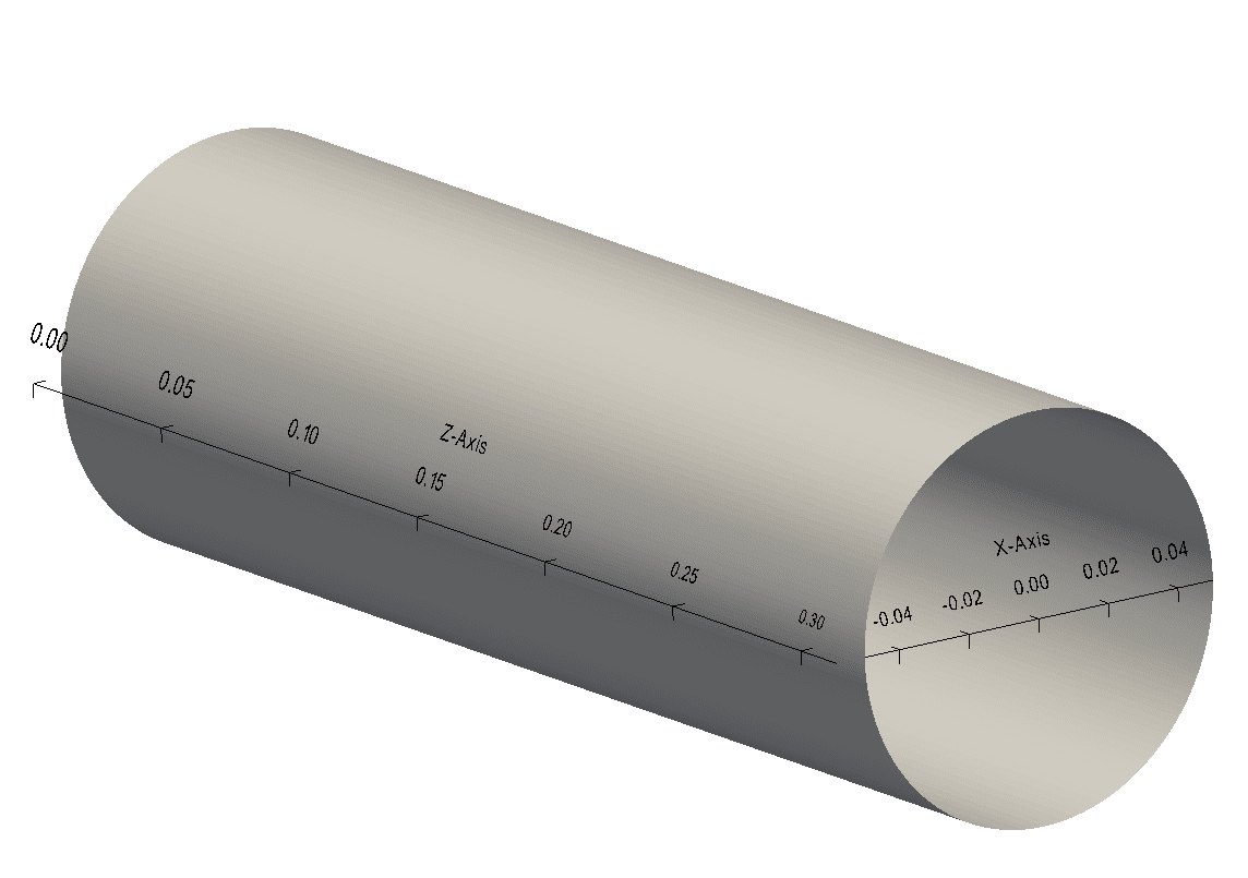
The geometry of the study is a straight cylindrical body (see Figure 1). A brief description of the dimensions is provided by the table below.
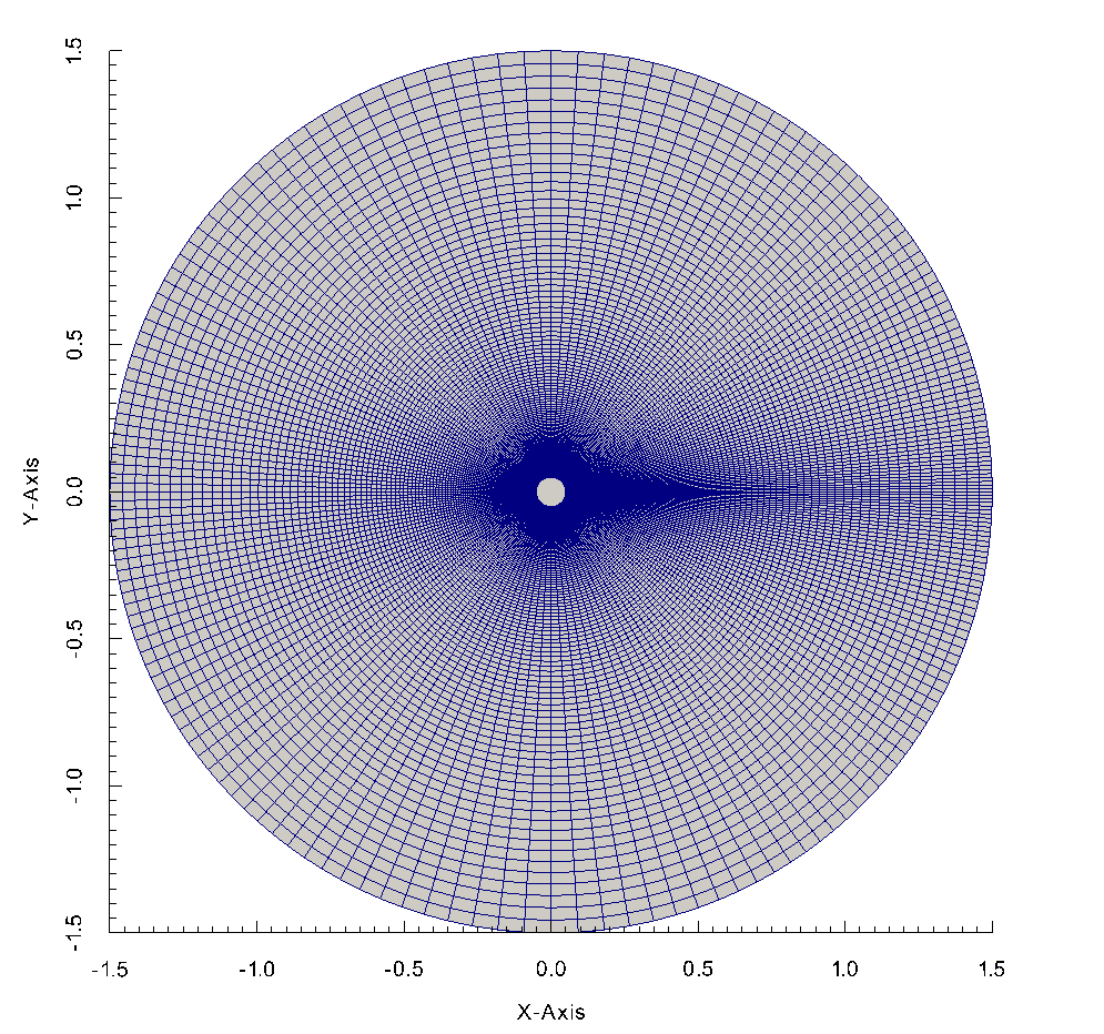
An O-type domain is selected as the flow domain around the cylinder. For cylinder diameter \(D\), the domain is 15 \(D\) in the radial direction and \(\pi D\) in the span-wise direction (see Figure 2).
Dimensions are given below
| Dimension | Value \([m]\) |
|---|---|
| Cylinder Diameter | 0.1 |
| Domain Thickness | 0.314 |
| Domain Diameter | 3 |
Tool Type: OpenFOAM®
Analysis Type: Transient, Incompressible with LES Smagorinsky turbulence model.
Mesh and Element Types:
For this study, a structured hexahedral mesh was created with the open-source ‘BlockMesh-tool’. The grid nodes are distributed by a geometric grading in the radial direction. Further, the nodes are clustered near the stagnation point and in the wake region along the streamwise direction. The mesh is based on a y-plus \((y+)\) criterion of \(y+\)<1 in the radial direction. The complete details of the mesh are listed in Table 2:
Fluid:
Boundary Conditions:
The inlet boundary was set as a non-turbulent fixed velocity condition, while a pressure boundary condition was applied at the outlet. For the spanwise boundaries, a symmetry condition was applied. The following table provides further details.
| Boundary Surface | Velocity | Pressure |
| Inlet | Fixed value of 0.59 \(m/s\) | Zero gradient |
| Outlet | Inlet-outlet | 0 \(Pa\) Fixed value gauge pressure |
| Cylinder Wall | Fixed value of 0 \(m/s\) | Zero gradient |
| Front and back faces | Symmetry | Symmetry |
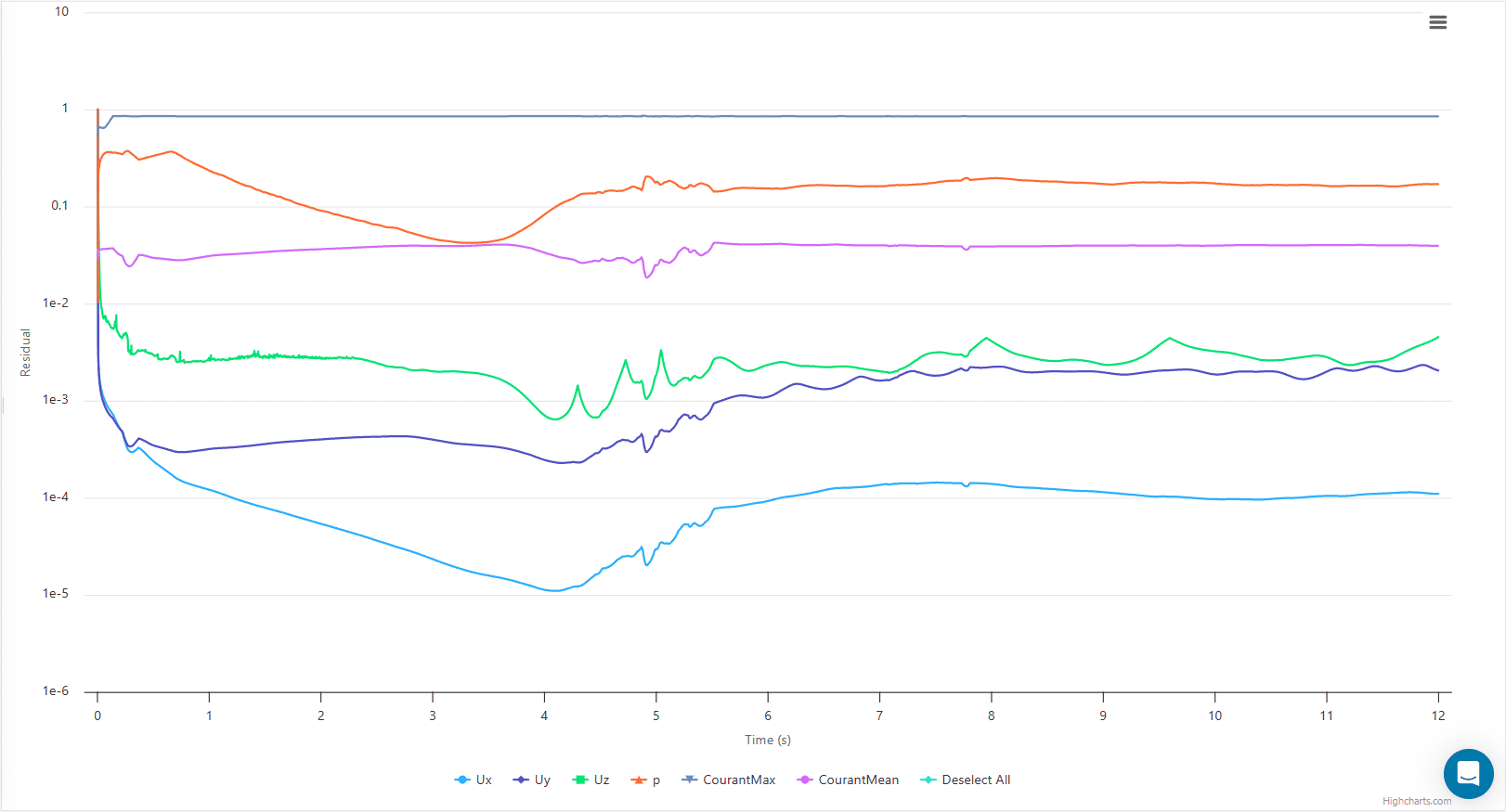
To ensure meaningful results, it was ensured that the simulation was run for at least 3 fluid passes. The distance from the cylinder to the outlet is 1.5 \(m\). Thus, for the 0.59 \(m/s\) inlet velocity, 3 fluid passes would take approximately 8 seconds. The simulation was run for 12 seconds to achieve trustworthy results.
The convergence plots seem to find an acceptable stability after 7 seconds. Since this is a transient simulation with eddies resolved, it was important to find the mean value of the comparing variables over the final few time steps (8-12 seconds).
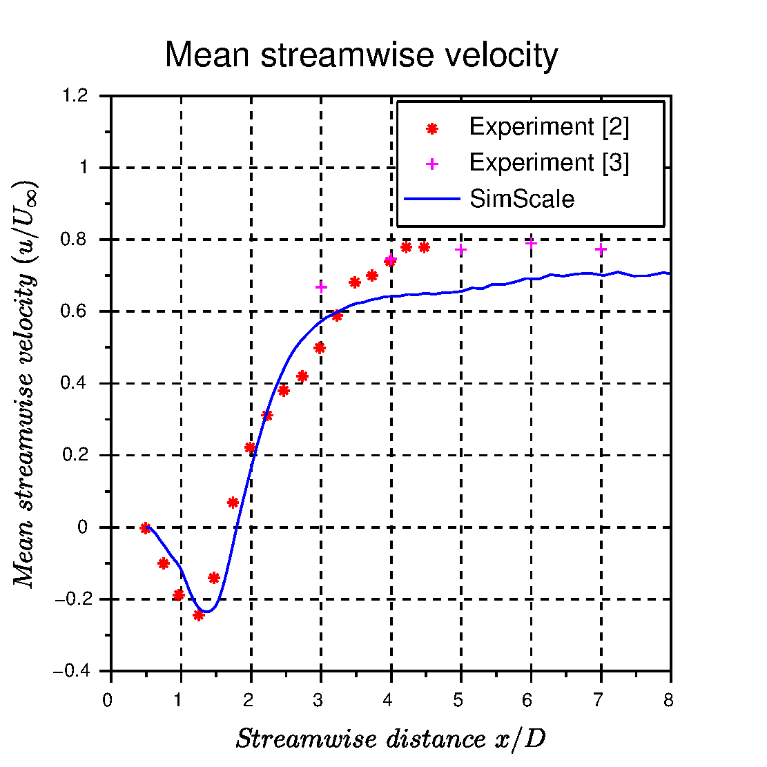
The mean stream-wise velocity profile was calculated by averaging the x-component of the velocity at time steps 8, 9, 10, 11, and 12 seconds. This is compared with experimental data provided by L.Ong and J.Wallace\(^2\), and L.M.Lourenco and C.Shih\(^3\) as shown in Figure 4.
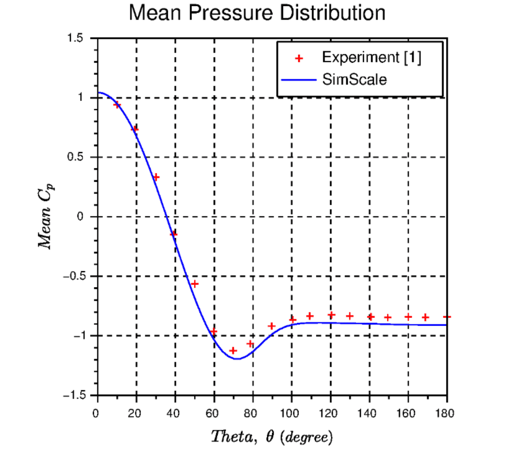
A comparison of the mean pressure distribution obtained with SimScale and experimental data provided by C.Norberg\(^1\) is given in Figure 5.
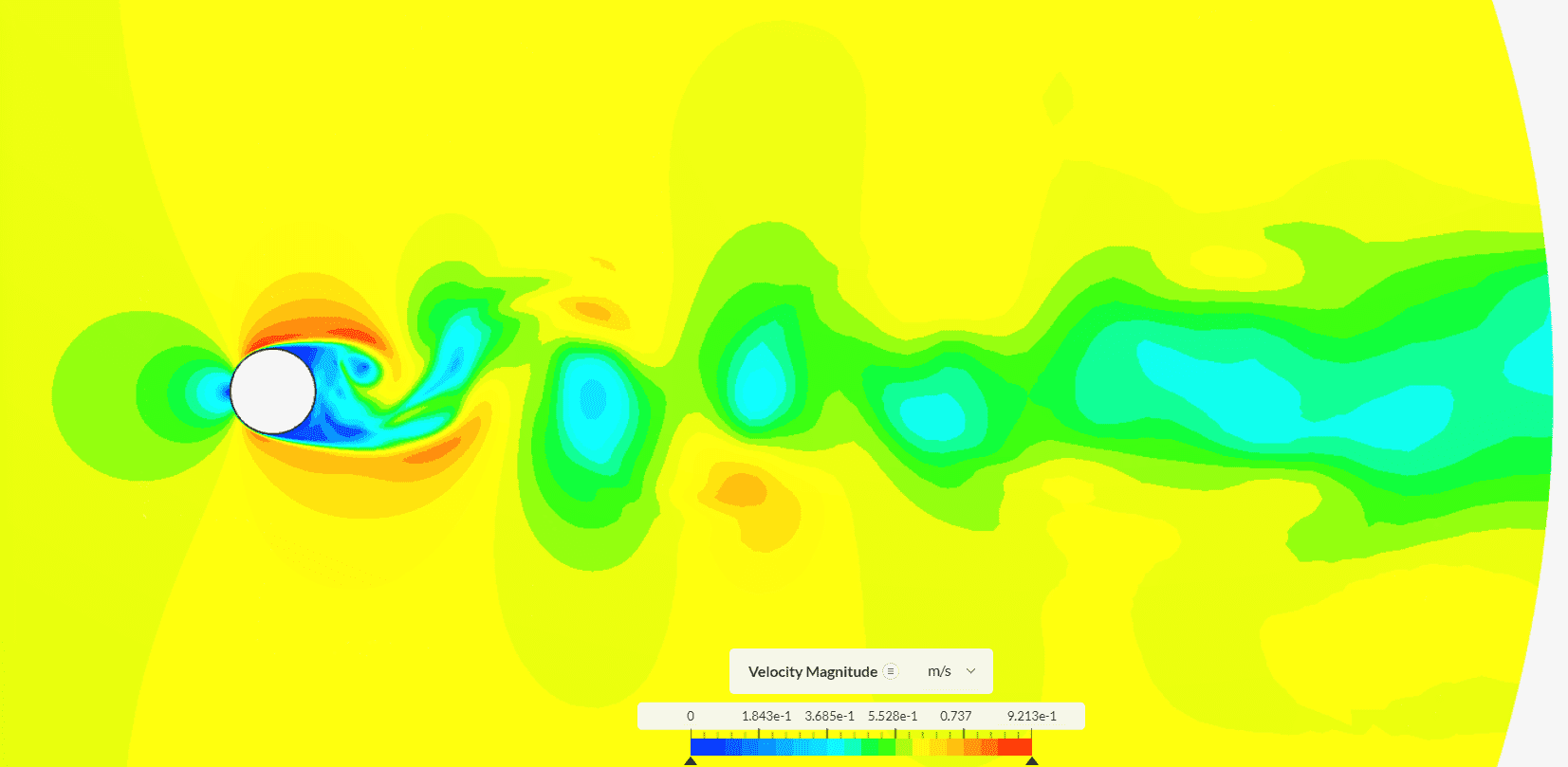
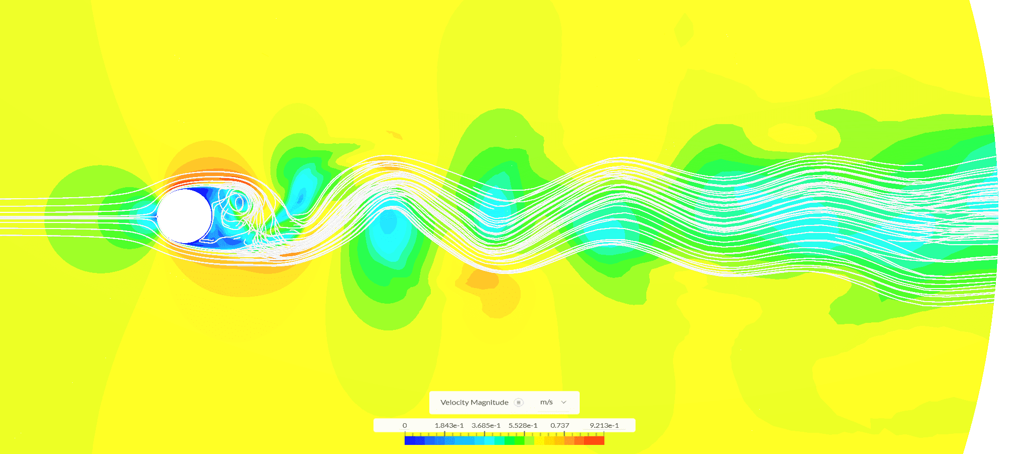
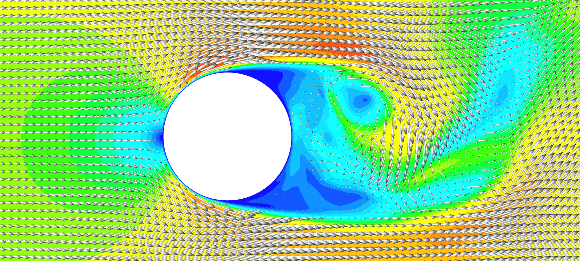
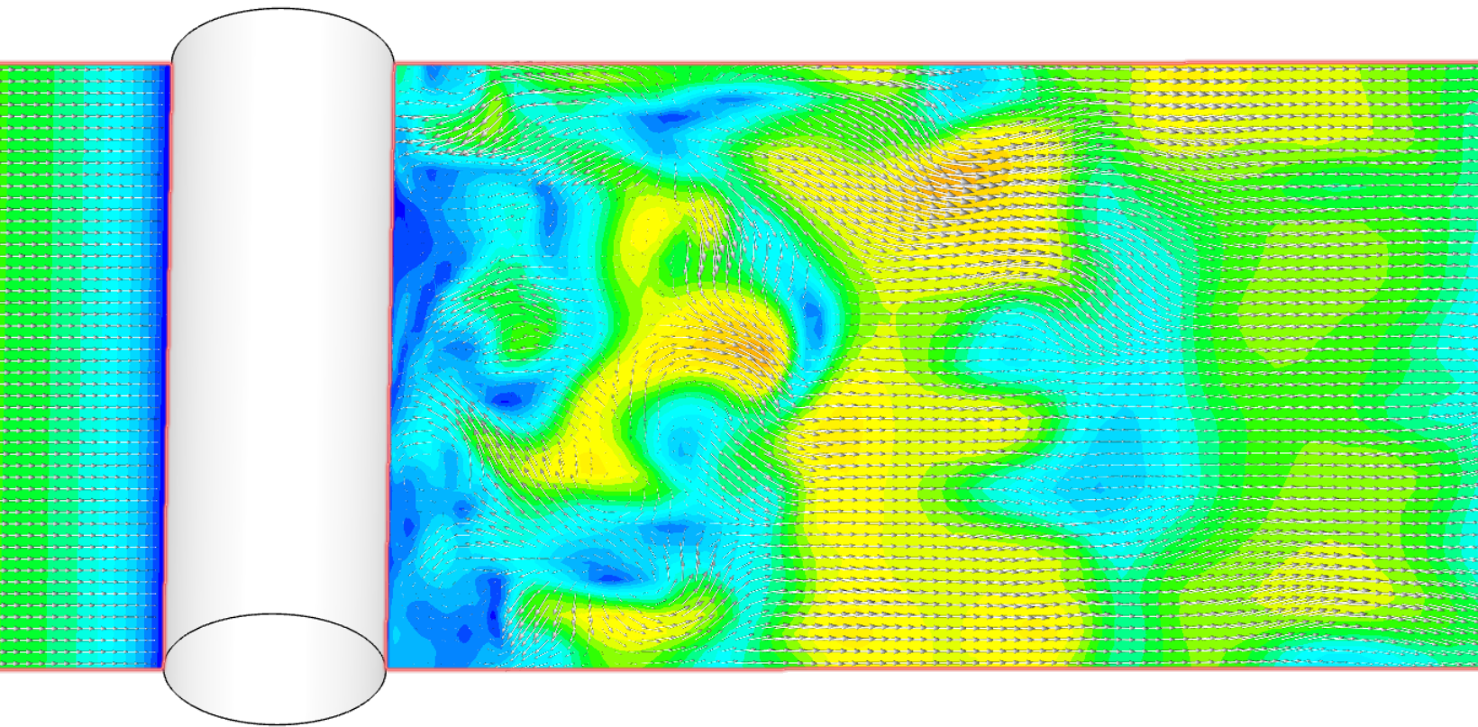
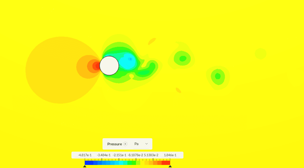
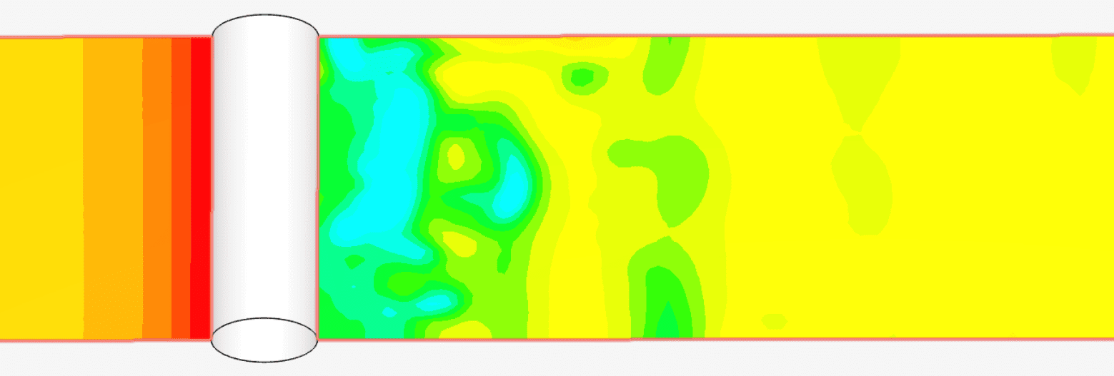
A visualization of the instantaneous flow field for the velocity and pressure fields of the LES cylinder validation case is shown in Figures 6 to 10, along the cross-sectional and spanwise planes, at a time step of 9 seconds.
References
Last updated: July 18th, 2025
We appreciate and value your feedback.
Sign up for SimScale
and start simulating now