Documentation
This validation case belongs to solid mechanics. The aim of this test case is to validate the following parameter:
The simulation results of the cloud-based simulation platform SimScale were compared to the results presented in [HPLA100]\(^1\).
The geometry used for the case is as follows:
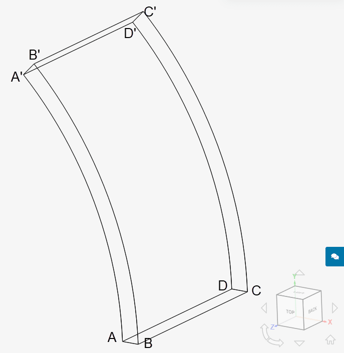
The solid body is created by rotating face ABCD by 45° and due to the symmetry of the cylinder, only one-quarter of the cylinder is modeled.
The coordinates of points A, B, C, and D can be seen below:
| Point | X | Y | Z |
| A | 0.0195 | 0 | 0.01 |
| B | 0.0205 | 0 | 0.01 |
| C | 0.0205 | 0 | 0 |
| D | 0.0195 | 0 | 0 |
Tool Type: Code_Aster
Analysis Type: Static
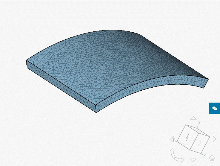
Mesh and Element Types:
The mesh was created with the Standard meshing algorithm in SimScale.
| Case | Element Type | Number of Nodes | Element Technology |
| A | 1st Order Tetrahedral | 3242 | Standard |
| B | 2nd Order Tetrahedral | 20965 | Reduced Integration |
Material:
Initial and/or Boundary Conditions:
The reference solutions for stress and displacement is calculated with the equations below:
$$ u(r)=\frac{−(1+\nu)(1−2\nu)}{(1−\nu)E}\rho\Omega^2\frac{r^3}{8}+Ar+\frac{B}{r}\tag{1} $$
$$\sigma_{zz}(r) = \frac{-\nu}{1-\nu}\rho\Omega^2\frac{r^2}{2}+\frac{2 \nu E}{(1+\nu)(1-2\nu)}A\tag{2}$$
$$A = \frac{(3-2\nu)(1+\nu)(1-2\nu)}{4(1-\nu)E}\rho\Omega^2R^2(1-x^2) = 7.13588\times 10^{-12} \ mm^2\tag{3}$$
$$B = \frac{(3-2\nu)(1+\nu)(1-2\nu)}{8(1-\nu)E}\rho\Omega^2R^4(1-x^2)^2 = 3.561258\times 10^{-15} \ mm^2\tag{4}$$
$$x = \frac{h}{2R} =\frac{0.001 \ m}{2\times0.02 \ m} = 0.025\tag{5}$$
Term \(h\) is the thickness of the cross-section and \(R\) is the radius of the middle surface of the cylinder and both are in meters (\(m\)).
The rotational force is validated by comparing the displacement \(u_r\) in meters \(m\) and Cauchy stresses \(\sigma_{zz}\) in \(N/m^2\) obtained from SimScale against the reference results obtained from [HPLA100] is given below:
| Case | Quantity | HPLA-100 | SimScale | Error [%] |
| A | \(u_r(r\) = 0.0195 \(m)\) | 2.9424e-13 | 2.939e-13 | -0.109 |
| A | \(u_r(r\) = 0.0205 \(m)\) | 2.8801e-13 | 2.877e-13 | -0.113 |
| A | \(\sigma_{zz}(r\) = 0.0195 \(m)\) | 0.99488 | 0.990826 | -0.407 |
| A | \(\sigma_{zz}(r\) = 0.0205 \(m)\) | 0.92631 | 0.931388 | +0.548 |
| B | \(u_r(r\) = 0.0195 \(m)\) | 2.9424e-13 | 2.942E-13 | -0.001% |
| B | \(u_r(r\) = 0.0205 \(m)\) | 2.8801e-13 | 2.880E-13 | -0.001% |
| B | \(\sigma_{zz}(r\) = 0.0195 \(m)\) | 0.99488 | 0.995056 | +0.018 |
| B | \(\sigma_{zz}(r\) = 0.0205 \(m)\) | 0.92631 | 0.926469 | +0.017 |
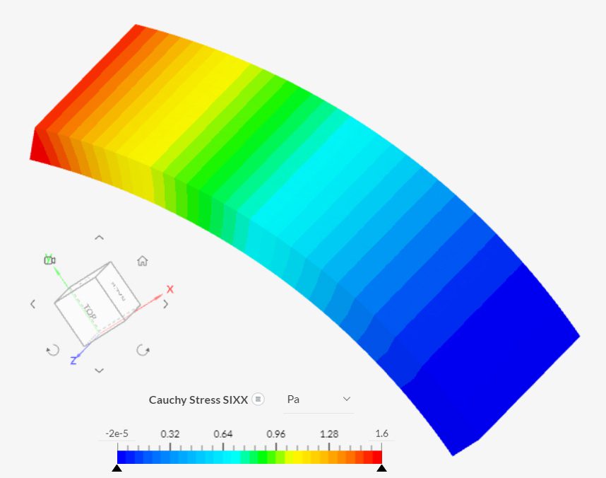
The stress experienced by the cylinder under the rotational force can be seen below:
Note
If you still encounter problems validating your simulation, then please post the issue on our forum or contact us.
Last updated: November 16th, 2022
We appreciate and value your feedback.
Sign up for SimScale
and start simulating now