Validation Case: 3D Triaxial Displacement Secondary Creep (NAFEMS Test 6(b))
The secondary creep validation case belongs to solid mechanics. This test case aims to validate the following parameters:
- Creep material behavior
- Standard and reduced integration elements
- Automatic time stepping
The simulation results were compared to the results presented in [NAFEMS]\(^1\).
Geometry
The geometry consists of a cube with an edge length \(l\) = 0.1 \(m\).
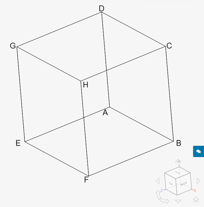
The coordinates for the points in the cube geometry are as tabulated below:
| A | B | C | D | E | F | G | H | |
| x | 0 | 0.1 | 0.1 | 0 | 0 | 0.1 | 0 | 0.1 |
| y | 0 | 0 | 0.1 | 0.1 | 0 | 0 | 0.1 | 0.1 |
| z | 0 | 0 | 0 | 0 | 0.1 | 0.1 | 0.1 | 0.1 |
Analysis Type and Mesh
Tool Type: Code Aster
Analysis Type: Nonlinear static
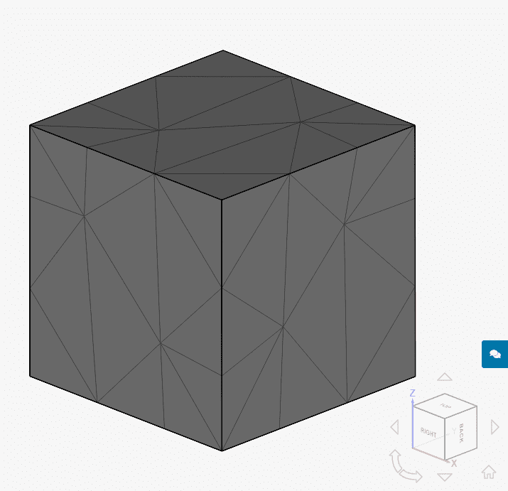
Mesh and Element Types: The mesh for cases A through D is a second-order tetrahedral mesh, generated in SimScale by the standard algorithm.
| Case | Mesh Type | Number of Nodes | Element Type | Creep Formulation | Element Technology |
| A | Standard | 235 | 2nd order tetrahedral | Norton | Standard |
| B | Standard | 235 | 2nd order tetrahedral | Norton | Reduced integration |
| C | Standard | 235 | 2nd order tetrahedral | Time Hardening | Standard |
| D | Standard | 235 | 2nd order tetrahedral | Time Hardening | Reduced integration |
Find below the standard mesh used for cases A through D:
Simulation Setup
Material:
- Steel (linear elastic)
- Isotropic: \(E\) = 200 \(GPa\)
- \(\nu\) = 0.3
- \(\rho\) = 7870 \(kg/m³\)
- Creep formulation:
- Time hardening
- A: 8.681e-48 \(1/s\)
- N: 5
- M: 0
- Norton
- A: 8.681e-48 \(1/s\)
- N: 5
- Time hardening
Boundary Conditions:
- Constraints:
- Fixed value:
- Face ADEH: \(d_x\) = 0 \(m\)
- Face ABFE: \(d_y\) = 0 \(m\)
- Face ABCD: \(d_z\) = 0 \(m\)
- Displacement in x-direction
- Face BCGF: \(d_x\) = 0.3 \(mm\)
- Displacement in y-direction
- Face CDHG: \(d_y\) = 0.2 \(mm\)
- Displacement in z-direction
- Face EFGH: \(d_z\) =0.1 \(mm\)
- Fixed value:
Advanced Automatic Time Stepping
For all cases, the following advanced automatic time stepping settings were defined under Simulation control:
- Retiming event: Field change
- Target field component: Internal variable V1 (accumulated unelastic strain)
- Threshold value: 0.00005
- Timestep calculation: Mixed
- Field change target: 0.00004
Result Comparison
The secondary creep movement validation is done by comparing the stress (\(\sigma_{xx}\)) after a creep time of 1000 hours. Below you will find the SimScale and reference results from [NAFEMS]\(^1\):
| Case | NAFEMS R27 \([MPa]\) | SimScale \([MPa]\) | Error [%] |
| A | 1007.7 | 1008.23 | 0.053 |
| B | 1007.7 | 1008.23 | 0.053 |
| C | 1007.7 | 1008.23 | 0.053 |
| D | 1007.7 | 1008.23 | 0.053 |
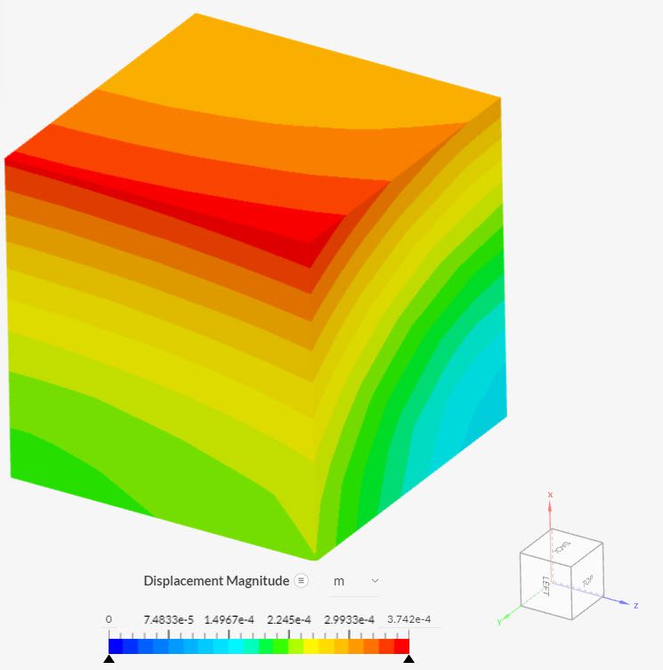
In all configurations, the results obtained with SimScale show a good agreement with the reference values. The displacement of the geometry can be seen below:
Note
If you still encounter problems validating your simulation, then please post the issue on our forum or contact us.
Last updated: November 29th, 2023
Did this article solve your issue?
How can we do better?
We appreciate and value your feedback.


