Joule Heating
Joule heating describes the physical effect by which the passing of current through an electrical conductor releases thermal energy. The higher the electrical resistivity of the conducting material the higher the energy converted.
The effect of Joule heating can be intentional for example in electric heaters or undesired losses e.g. in busbars. The latter case requires accounting for the Joule heating effect when dealing with thermal management and cooling strategies.
SimScale allows you to define the electrical properties of conducting materials and electrical boundary conditions when enabled. The simulation takes the thermal losses of the electric circuits as input for the thermal solution and computes Electric Potential, Current Density, and Joule Heat Generation as additional solution fields.
Enabling Joule heating is mainly required or useful if:
- the thermal power losses of electrical components are not known and therefore can not be modeled as a power source.
- the thermal power losses of electrical components are the main optimization interest e.g. electric heaters.
- the power losses are not uniformly distributed in the electrical conductor e.g. due to varying cross-sections.
- the electrical solution fields are of major interest e.g. judging voltage drops or optimizing current density.
Simulation Setup for Joule Heating
Global Settings
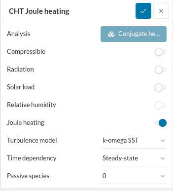
In order to include Joule heating in your analysis, switch on the toggle in the global settings panel. The option is available for Conjugate Heat Transfer v2 and Immersed Boundary Method simulations.
Materials
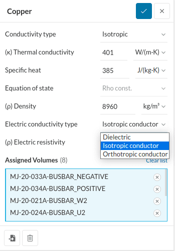
Joule heating only happens when current passes through a circuit and therefore only appears in electrical conductors. When Joule heating is enabled in the global settings each material gets an Electric conductivity type. It defines if the material is Dielectric (an electric insulator not conducting any current) or if it is a conductor. Isotropic conductors have the same resistivity opposing the current in all coordinate directions while Orthotropic conductors allow for differing resistivity.
For electric conductors, Electric resistivity needs to be provided. The resistivity is a measure of how much the conducting material opposes the current flowing through it. It is the reciprocal of electrical conductivity and is more commonly used. It is given in \(Ohm*m\) which means that the further the current needs to pass through the material the higher the resulting total resistance will be and the larger the available cross-section area the lower it will turn out.
Note
Note that when you import materials from the library they come with the typical electrical properties for this material but can still be adjusted.
Fluids are always considered dielectric materials and therefore do not participate in the electrical solution.
Boundary Conditions
As electric current flow is only supported for solid materials, you can add electrical conditions on wall boundary conditions. You can define either Current inflow or outflow boundary conditions in Amperes or an Electric potential in Volts on a boundary. If the wall doesn’t have any known electric conditions you can keep the default (None) which defines 0 current flow across the boundary.
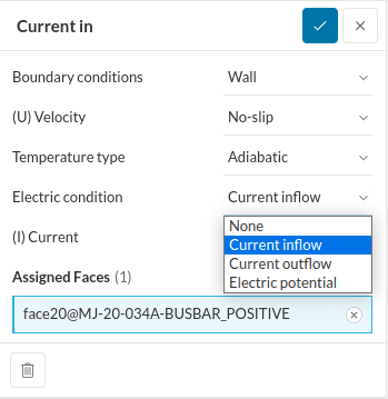
Electric boundary conditions define the flow in an electric circuit and can be chosen to either
- define current inflow and outflow with at least one electric potential boundary condition as a reference potential.
- define electric potentials on boundaries only that will define the resulting currents based on the potential drops.
Important
It is not possible to define only inlet and outlet flow conditions even if the integrated flux into and out of the domain is in balance due to potential numerical instabilities. Defining at least one reference potential resolves the over-constrained system and will result in the expected in or outflow at the respective boundary.
Numerics
For joule heating problems, additional settings can be changed within the numerics. For further details check out this joule heating numerics page.
Related Fields
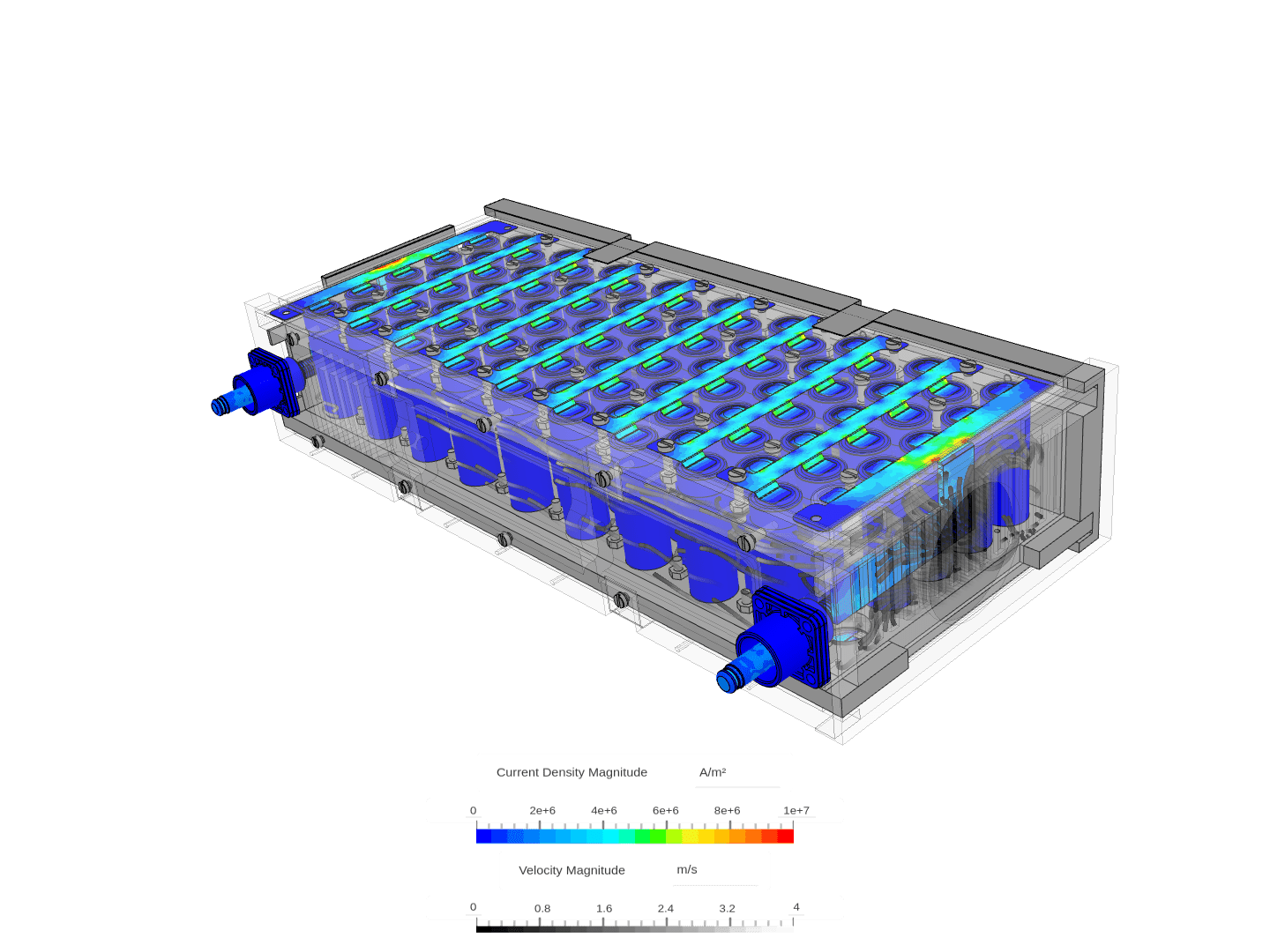
The electric solution is calculated by resolving the Electric Potential in all conducting materials of the domain. The Current Density and Joule Heat Generation fields are derived from the potential solution.
- Electric Potential: The Electric Potential field is solved including the material resistivity of the conducting materials and shows the potential difference across the domain. If your model only covers part of an electric circuit with a prescribed current flow, the resulting potential difference will be the potential drop in the system.
- Current Density: The gradient of the Electric potential is causing the current flow in the electric conductors. The current density provides the local distribution of current in the conducting materials as a 3-dimensional vector field and is provided in \(A/m^2\). You can use the statistical post-processing tool to calculate the resulting total current flow across a cross-section of the conductor.
- Joule Heat Generation: The local current density combined with the resistivity of the material defines the thermal power loss due to Joule heating and is given as \(W/m^3\). Note that the electric current enters the equations by the power of two in Ohm’s law. The dissipated power, therefore, scales exponentially with the current. You can use the statistical post-processing tool to calculate the resulting total power loss inside a conductor part.
$$ P = R I^2 $$
where,
\(P\) = power loss,
\(R\) = resistance,
\(I\) = current.
Limitations
Known limitations are:
- Fluids are always considered dielectric materials and don’t participate in the electric solution.
- Electrical result fields are currently not included under the result control plots.
- Electrical resistivity can not be provided dependent on temperature. As electrical resistivity can change significantly based on the thermal surroundings it is important to adjust the value if the initial simulations result in unexpectedly high or low temperatures.
- Electric contact resistances can not be added as it is possible for thermal resistances. They need to be modeled in 3D or disregarded in the calculation.
- Electric boundary conditions can only be applied in a steady fashion and can not be provided as a time-dependent input.
Last updated: June 28th, 2024
Did this article solve your issue?
How can we do better?
We appreciate and value your feedback.


