Velocity Inlet and Velocity Outlet
The velocity inlet and outlet boundary condition (BC) defines the flow getting into or out of the domain at a certain velocity. As described below, different possibilities are available to define it.
Velocity Inlet
The inlet pressure and total (stagnation) values are not fixed but calculated, with the pressure gradients fixed to zero.
For incompressible flows, the temperature properties are not required, while for compressible flows, the temperature at the inlet must also be defined. The turbulent flow quantities are matched with the values specified for the initial condition and are thus not required as inputs.
Important
When using a velocity inlet boundary condition, at least one pressure boundary condition should be specified for stability, e.g., a pressure outlet boundary condition.
For external flows, it is generally recommended to place the velocity inlet at a specific distance upstream of the body, to avoid non-physical effects.
Velocity Outlet
The static (gauge) pressure is not fixed and will be calculated to reach the required value based on the velocity profile at the outlet. Analogous to the outflow boundary conditions, all relevant scalar quantities are calculated from the interior with gradients fixed to zero.
Analysis Types
The velocity inlet and outlet boundary conditions are available under all CFD analysis types such as:
- Incompressible
- Compressible
- Multiphase
- Multi-purpose
- Convective Heat Transfer
- Conjugate Heat Transfer
- Conjugate Heat Transfer (IBM)
Velocity Types
The flow velocity can be defined as:
- Fixed value
- Mean value
- Flow rate
- Mean flow rate
- Face normal value
- Freestream
- Outlet mean phase
These input values can either be fixed or driven by a formula or a table for space or time-dependent conditions.
Face Normal Value
Please be aware that the Face Normal Value is only available for the velocity outlet boundary condition.
Fixed Value
The Fixed value type prescribes the velocity magnitude and direction on the selected surface(s). It is fixed by defining each velocity component in the x, y, and z directions. Here is an example of how to assign a velocity entering an inlet at 10 \(\frac{m}{s}\) in the x-direction:
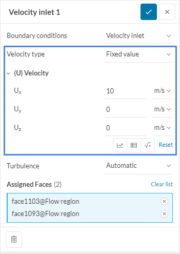
Every region of the boundary would have the same velocity value unless it is formula or table-driven.
Mean Value
This is more often used at an outlet where it is not clear whether the flow passes through the boundary uniformly. The average of the flow over the boundary would be equal to a specified value. Unlike the fixed value BC, not every region on the boundary will necessarily have the same value. The depicted boundary condition is a typical example and would apply to both internal flow (a pipe, for example) and external flow (a building, for example).
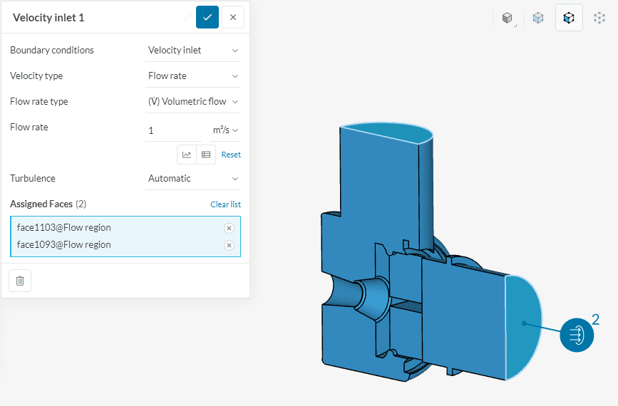
Flow Rate
The flow rate sub-type is available for both velocity inlet and outlet. The values that are input by the user must be positive. The direction of the velocity will be determined by the boundary condition chosen. If it’s a velocity inlet flow rate, then flow goes into the domain. If it’s a velocity outlet flow rate, then the flow will leave the domain.
When used for the inlet, this boundary condition calculates velocity at the boundary based on the provided flow rate. Both mass and volumetric flow rate can be prescribed as input values. If a mass flow rate is assigned, the fluid density specified within the material would be used. The flow is assumed normal to the boundary.
When used for the outlet, the software will determine what pressure gradients are necessary to achieve the defined mass or volumetric flow rates.
Important
1. It is not recommended to use this boundary condition with “Potential foam initialization” enabled in Simulation Control.
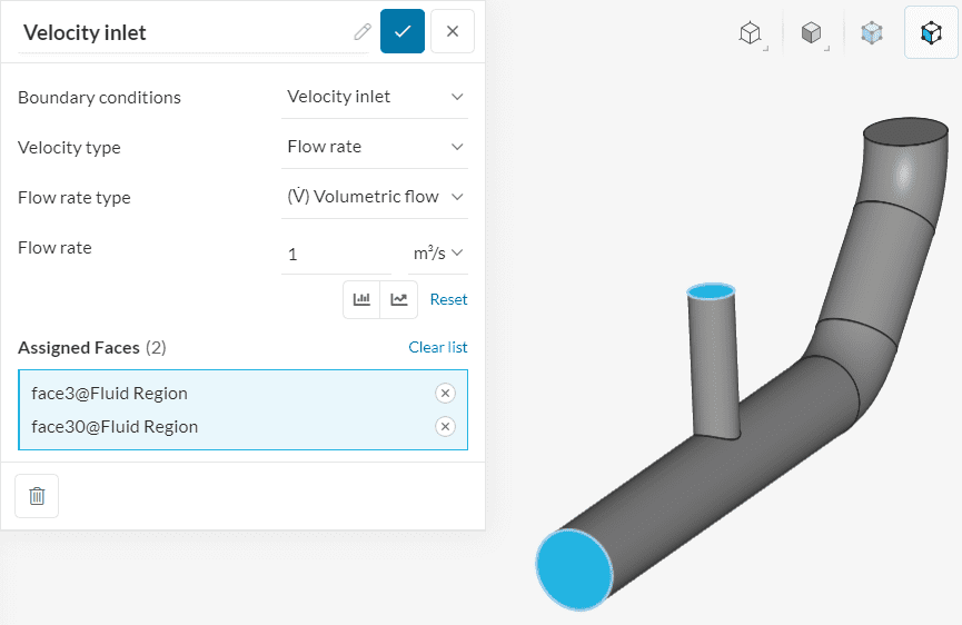
2. A flow rate boundary condition assigned to more than one surface of the fluid domain means that each surface receives the specified flow rate.
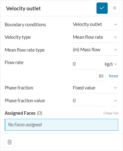
Mean Flow Rate
This is an outlet-only boundary condition available for the Multiphase analysis type. The average mass or volumetric flow rate over the boundary defines the velocity outlet. The assigned values must be positive.
Face Normal Value
This is an outlet-only boundary condition. The input value defines a target face’s normal mean outlet velocity. Then, the pressure gradients necessary to achieve the prescribed mean velocities are calculated by the software.
Note that the mean velocity value is considered normal to the surface. For this boundary condition, the input must be positive.
Freestream
This boundary condition has two different possibilities. When the flow at the boundary is leaving the domain, a zero gradient condition is applied. Otherwise, a fixed velocity is assigned. The flow direction is based on the input values.
The user should provide this value as an input when the boundary is far from the object. Based on velocity, the free stream pressure at the boundary is then calculated by applying a zero gradient condition to constrain the flux. For compressible flows, temperature values must be provided as well. The turbulent flow quantities at the free stream boundary are matched with the values specified for the initial condition and are thus not required as inputs.
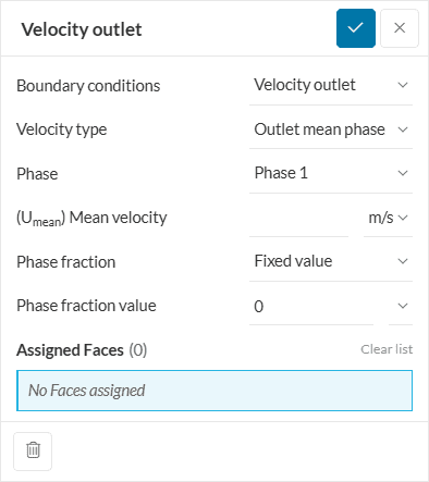
Outlet Mean Phase
This is an outlet-only boundary condition available for the Multiphase analysis type. This is used when the phase of the flow at the outlet boundary is not unique but the mean phase can be approximated. Mean velocity is also required.
Turbulence
SimScale allows for the definition of turbulence at the velocity inlet. The user has three options to choose from.
- Automatic
- Turbulent intensity and mixing length
- Fixed Value
The values can either be fixed or driven by a formula or a table for space or time-dependent conditions.
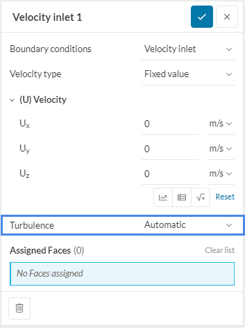
Automatic
When Automatic turbulence is assigned a fixed turbulence value of 5 \(%\) is chosen for the turbulent intensity \((I)\). The turbulent mixing length \((L)\) is calculated as 0.07 \((D_{h})\), where \((D_{h})\) is the hydraulic diameter of the boundary face.
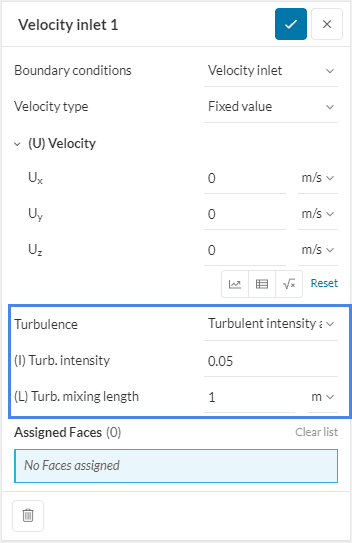
Turbulent Intensity and Mixing Length
When the Turbulent intensity and mixing length option is selected, the user can specify the turbulent intensity \((I)\) and the turbulent mixing length \((L)\).
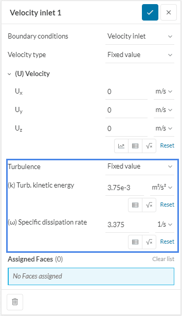
Turbulence Fixed Value
Fixed Value allows the user to directly specify the turbulent kinetic energy \([\frac{m^2}{s^2}]\) and the specific dissipation rate \([\frac{1}{s}]\).
Velocity Inlet and Velocity Outlet Parametrization
SimScale supports the parametrization of velocity inlet and outlet boundary conditions. This article provides an overview of parametric capabilities in the platform and the setup workflows.
Velocity Inlet (Incompressible LBM)
In Incompressible LBM simulations, the velocity profile at the inlet of the flow domain can be defined with a Velocity inlet condition.
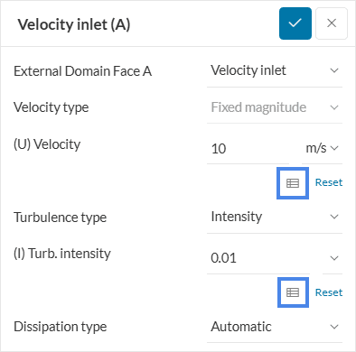
For the Velocity definition, two main options exist:
- Setting a uniform velocity, that is going to be applied to the entire inlet.
- By clicking on the icons highlighted in Figure 9, it is possible to define a height-dependent velocity profile, similar to the atmospheric boundary layer inlet boundary condition
For Turbulence type, two approaches are possible: Intensity and Turbulence kinetic energy. With the latter, the user explicitly defines the turbulence kinetic energy at the inlet (via uniform or table definitions).
The Turbulence Intensity represents a standard deviation between the velocity fluctuation and the average velocity of the flow.
$$I = \frac {u’}{U} \tag{1}$$
Where \(I\) is the turbulence intensity, \(u’\) is the velocity fluctuation and \(U\) is the average velocity of the flow. From the turbulence intensity, the solver calculates the turbulent kinetic energy (TKE) using equation 2:
$$TKE = \frac {3}{2} (u’)^2 = \frac {3}{2} (IU)^2 \tag {2}$$
Please note that the turbulence intensity is given in absolute values, therefore, defining a turbulence intensity of 0.01 is equivalent to 1%.
Last updated: August 4th, 2025
Did this article solve your issue?
How can we do better?
We appreciate and value your feedback.


