Documentation
In this chapter the main settings that are generally required as input for the Hex-dominant parametric mesher are detailed. These include defining the base domain size and discretization, several types of mesh refinements and their corresponding settings.
Many of the settings and refinements described below are similar to the settings described in the automatic Hex-dominant (only CFD) settings. However, one key difference is that the mesh cell size is defined as absolute length in the automatic meshing algorithm while it is defined via refinement levels here.
The Geometry Primitives by default contain the Background Mesh Box and the Material Point which must be specified by the user. Based on the requirements, additional geometries can be added (e.g. to define mesh refinement regions).
The Background Mesh Box specifies the bounding extents for the base mesh. The bounding extents must then be selected depending upon whether the user requires a mesh for External flow or Internal flow simulations.
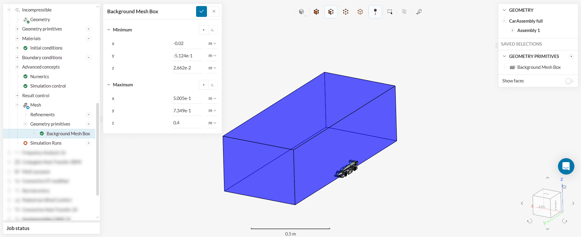
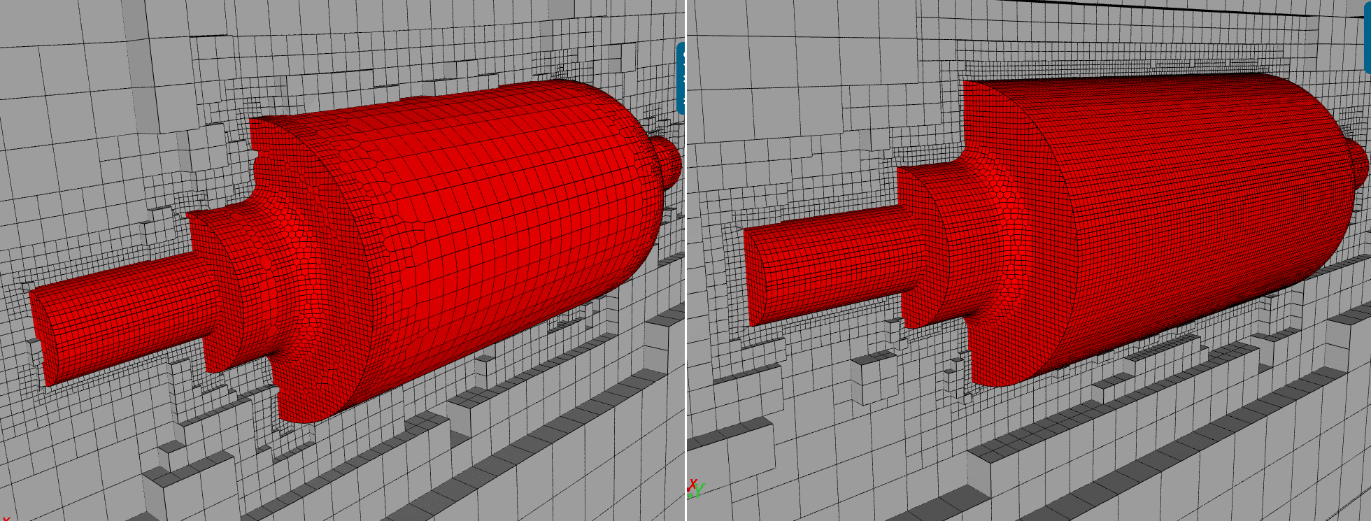
The material point is used to specify the enclosed space inside the Background Mesh Box that will be kept as the mesh in the Cell Removal part of Castellated Mesh step (see Background for snappy hex mesh). This will be the space which constitutes the final mesh.
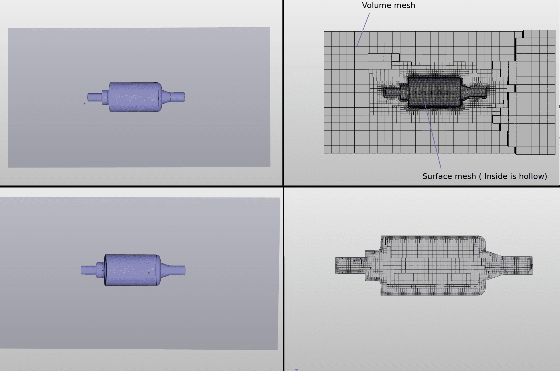
So, independent of the Background Mesh Box, the material point determines whether the resulting mesh is for an External flow simulation or Internal flow simulation. The figures below show two scenarios resulting from different specification of the material point for the same Background Mesh Box and object.
Important
The material point should never be located on a face, always inside a cell, even after refinements of the mesh. Therefore, coordinates ending in odd values should be preferred.
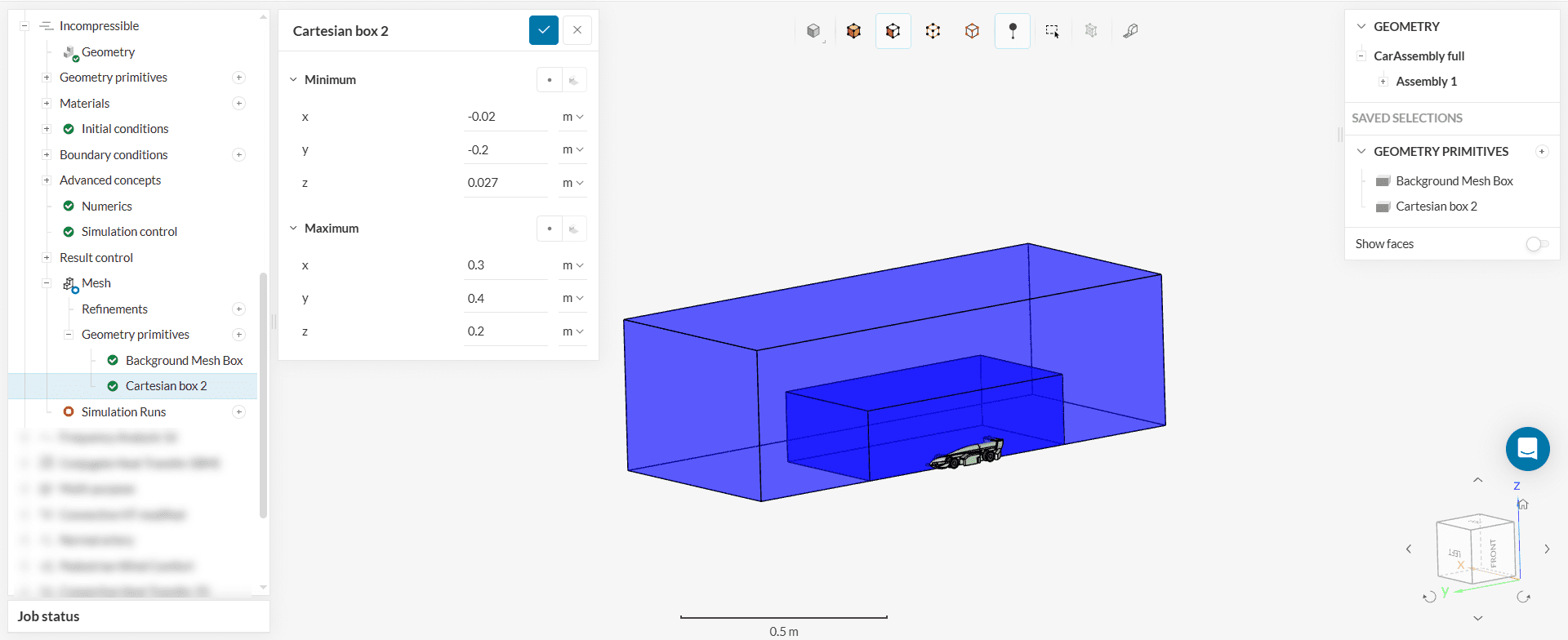
Additional geometries can be added by the user via the ‘+’ button on the Geometry primitives node in the mesh tree. These geometries can then be used to refine specific areas in the mesh to limit the extents of custom mesh refinements.
The following three types of shapes can be defined:
The figure below shows an example of a Cartesian box inside the Background Mesh Box and around the object.
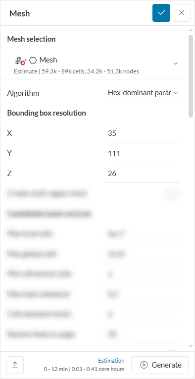
For the creation of the base mesh the user must specify the number of cells (for the Background Mesh Box) in each coordinate direction under Bounding box resolution.
The base mesh cell size (in X-direction) is then given as:
(Xmax-Xmin)/(Nx)
where, Xmax is the maximum X-coordinate, Xmin is the minimum X-coordinate of the Background Mesh Box and Nx is the number of cells in X-direction.
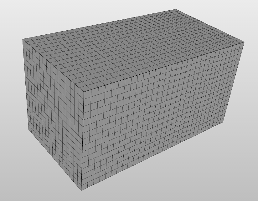
For the discritization it is recommended to have a base mesh with perfect cube cells to yield better results. This can be achieved if the following formulation holds:
(Xmax−Xmin)/Nx=(Ymax−Ymin)/Ny=(Zmax−Zmin)/Nz
Following the above formulation, a sample Base Mesh with perfect cube cells is shown in the figure below
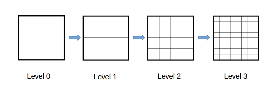
Based on the discretized Background Mesh Box, the Coarsest (largest) cell size is determined for each coordinate direction and is used to define a refinement of Level 0. This means that any Mesh refinements of Level 0 will have the same cell dimensions as the base mesh cell in respective coordinate directions.
Further, each increment of refinement level reduces the cell dimensions by half. With reference to
ΔXn=ΔXo/2^n
This refinement levels are illustrated by the figures below:
Important
It is recommended that the maximum level be set to achieve a minimum cell size in the order of the minimum geometry dimension. Refinement Levels are not limited, you are able to specify any level of refinement (e.g. level 10), but this may result in a overly large mesh size.
For the SnappyHexMesh, several refinement option can be selected by the user to get the required mesh. These are all specified under the Mesh Refinement sub-tree. Each refinement plays a specific role in the meshing process that is briefly described below:
The settings and parameters for each type of refinement are described in detail below.
The surface refinement is done only for the selected surfaces. If the user assigns a volume to the surface refinement, the refinement is applied to all surfaces of that volume. Surface refinement can also be used to group cells together – such a group of cells is called a cell zone.
The user must specify two refinement levels, level min and level max. The minimum level is applied first across all of the surfaces. The maximum level is only applied to cells in areas where the normals form an angle greater than the specified resolve feature angle (in Advanced Settings). Therefore, in the following cases, only the minimum level is applied.
Consequently, cells that get multiple intersections where the intersections form an angle larger than the resolve feature angle value get refined up to the maximum level.
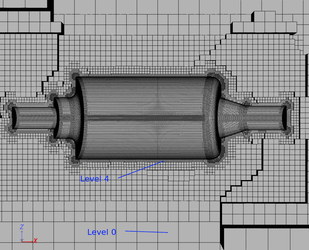
The figure below shows a mesh with surface refinement of minimum level = 2 and maximum level = 4.
Cell Zones
This option is by default inactive. If the user assigns a closed volume to this surface refinement and sets this option to Active, the refinement will group together all cells enclosed by this volume – such a group of cells is called a cell zone. It is then possible to assign different properties to a cell zone. For example, the user can set it as a rotating region (MRF (Multiple Reference Frame) or AMI (Arbritrary Mesh Interface)), a momentum source, a heat source or a passive scalar source. If the geometry that is being meshed is of STL format, the user can also assign a list of faces that form a closed volume to create a cell zone.
Important
It is recommended that the maximum level be set to give a cell size in the order of the minimum surface dimension. The surface refinement is overwritten by a feature refinement at the geometry edges by the specified feature refinement distance (see Feature refinement below for details).
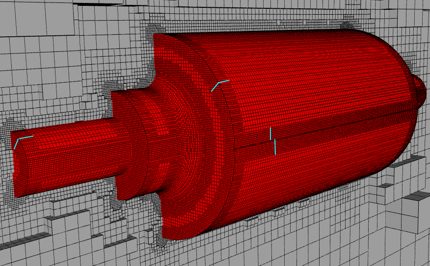
This refinement type is specifically important as it is used to refine the geometry’s feature edges. The feature edges are extracted based on the Included angle under Surface Feature Extract. So, the edges whose adjacent surface normals form an angle less than the included angle are marked for extraction and refinement.
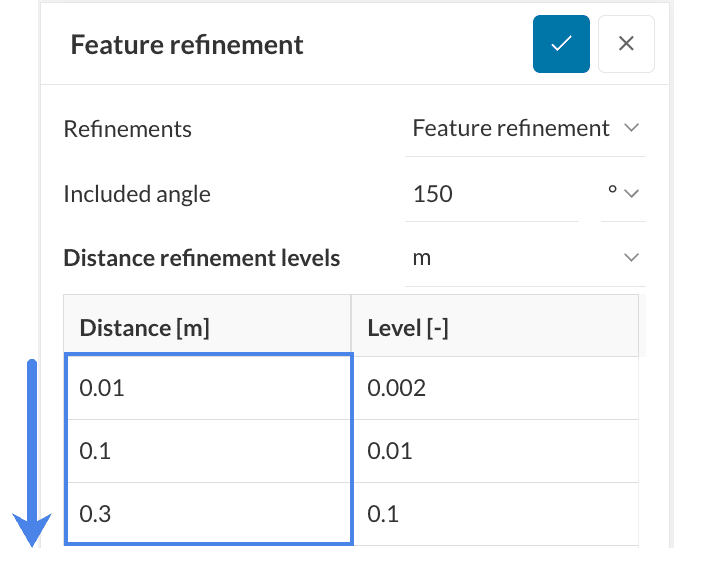
The user must specify the Distance and the Level. The edge and surface mesh will then be refined up until the specified distance in all directions from the extracted edges as depicted by the figure below.
Keep in mind
The values for the “Distance” input should be written from smallest to largest, as shown below:
Important
This feature refinement is based on the explicit Feature Snap method that provides better conformation. If this refinement is not used, an implicit feature Snap is used by default. (see Snap Controls in Advanced Settings for details)
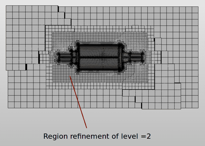
The region refinement is used to refine the volume mesh for one or more user-specified volume regions under geometry primitives or geometry regions. One of the following refinement modes can be applied to each region:
In the case of inside and outside refinement, the distance is not required and will be ignored. The level then determines the cell size relative to the Base Mesh cell size.
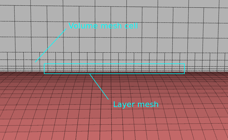
The layer refinement adds a volume mesh with cells aligned to the surface. The user must enter the following 4 basic parameters:
The values need to be specified relative to the neighboring volume cell size after refinements. The figures below shows sample image of layers along an object’s surfaces.
The Bounding box layer addition refinement is similar to the Layer refinement but only applicable to the bounding box. This is mainly useful for external flow analysis where the box surface acts as a wall for the flow domain and must be refined with a layer mesh for accuracy. The user must select one additional parameter, which is the box face for layer generation.
References
Last updated: June 2nd, 2025
We appreciate and value your feedback.
What's Next
Advanced Settings for Hex-Dominant Parametricpart of: Hex-dominant
Sign up for SimScale
and start simulating now