Bolt Preload
With the Bolt Preload boundary condition, an axial force is applied on one or more cylindrical bodies, and then the resulting length of the cylinder is fixed, all before the other load boundary conditions are applied to the model. This technique is useful to model the loads and interactions related to the tightening of bolted connections.
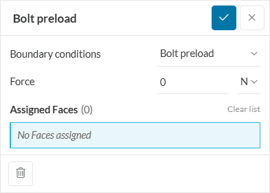
The parameters of the boundary condition are:
- Force: The preload force acting on each of the bolts.
- Assignment: Cylindrical faces that represent the shanks of the bolts under the preload force. These cylindrical faces should be
- continuous,
- not be assigned to bonded contact definitions,
- can be assigned to physical contact definitions
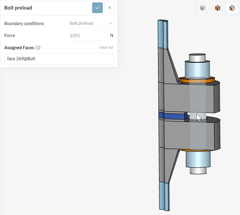
See Figure 2 below for illustration:
Supported Analysis Types
The following analysis types support the usage of this boundary condition:
Bolt Preload Method
In bolted connections, the tightening torque applied on bolts creates an initial stress state both on the bolts and on the connected parts. This effect is called bolt pre-tension or bolt preload. As this stress state is present before the components start to perform their structural function, it is wrong to assume that all loads happen at the same time, creating a non-linear situation.
On the other hand, as this stress is created purely from the internal reaction of the bolt against the imposed stretch due to tightening, it can not be modeled by an external force or action.
The methodology implemented in SimScale for the bolt preload boundary condition is known as the bolt force method, and works as follows:
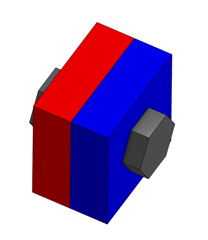
- Model preparation: The bolt shank is split in half, creating two coinciding circular faces at the middle of the cylinder.
- Preload step 1: The force value is applied to the newly created cut faces. A structural simulation is performed using only this force, and the resulting displacement of the cut faces is measured.
- Preload step 2: Apply the measured displacements to the cut faces and fix the resulting distance between the faces with a rigid connection.
- Proceed to the structural analysis with the remaining loads and the modified model from the step above, which captures the effect of bolt preload.
Last updated: February 28th, 2025
Did this article solve your issue?
How can we do better?
We appreciate and value your feedback.


