This article aims to explain and show how to switch between constant time step control and adjustable time step control in transient CFD simulations.
What is the Time Step in Transient Simulations?
In transient CFD simulations, we simulate the flow in real-time. This is solved by starting at \( t = 0 \) and using time increments \( \Delta t \) to calculate the next time step.
$$ \ t_{n+1} = \ t_{n} + \Delta t \tag{1} $$
Where:
- \( t_{n+1} \) is the next time step
- \( t_{n} \) is the current time step
- \(\Delta t \) is the time increment
Constant Delta T
The first option is to set \( \Delta t \) to a constant value, which means that \( \Delta t \) will not change throughout the transient simulation. To set up \( \Delta t \) as constant, open the simulation control panel and set Adjustable time step to False.
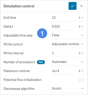
If the flow field is assumed to be mostly constant/stable in time and transient effects are restrained to the temperature field, a fixed time step for the complete simulation can be chosen. This gives users more direct control of the simulation.
Adjustable Time Step
In addition to the constant time increment \( \Delta t \), you can use an Adjustable time step approach, where SimScale will calculate the next time step \( \Delta t _{n+1}\) based on a desired Courant number \( C \) . The Courant number is defined as:
$$ C = u \frac{\Delta t}{\Delta x} \tag{2} $$
Where:
- \( C \) is the Courant number
- \( u \) is the fluid velocity in a given cell
- \( \Delta t\) is the time increment
- \( \Delta x\) is the cell length
For multiphase simulations, the Courant number \( C \) should stay below 1 \(( C <1 )\) due to an explicit time integration approach used for the phase fraction. Other analysis types use implicit methods for time integration, which allows the Courant number to be pushed beyond 1. These scenarios are explored in the following article:
The image below shows the simulation control panel when adjustable time step is true:
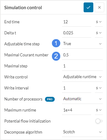
If the flow field in the simulation domain is expected to show relevant transient behavior, then an Adjustable time step and a maximal CFL number should be chosen. As such, the solver reacts to transient velocity peaks that might introduce instabilities or inaccuracies by reducing the time step. This way, when the velocity reduces, the time step is increased again ensuring a minimal simulation run time.
Starting Time Step for Adjustable Time Steps
In the SimScale Simulation Control Panel, the Adjustable time step is active per default. Note that the user can still choose the \( \Delta t\) value. At this point, the objective is to set a small value for Delta t, allowing the simulation to start as smoothly as possible.
A possible approach is to inspect the size of the mesh elements and estimate the velocity in the domain due to the boundary conditions. By using the equation 2 and assuming a value of Courant number equal to 1, we obtain the following:
$$ \Delta t_{1} < \frac{ \Delta x_{min}}{u} \tag{3} $$
Where:
- \( \Delta t_{1}\) is the first time step
- \( \Delta x_{min} \) is the smallest cell size
- \(u\) is the fluid velocity in a given cell
Note that using even smaller values for Delta t is possible for additional robustness. Since the Adjusted time step option is enabled, SimScale will automatically increase the time step size as the simulation progresses.
Ratio of Velocity to Mesh size
When adjustable time step is active, a high velocity \(u \) to cell size \( \Delta x\) ratio can result in a very small \( \Delta t\). This will lead to a very long simulation run time, which can cause the simulation to stop as maximum run time might reach before end time. In this case coarsening the mesh, or pushing the maximal Courant number further can help. Users are encouraged to run sensitivity studies and observe how results of interest change as the maximal Courant number is increased.
Note
If none of the above suggestions solved your problem, then please post the issue on our forum or contact us.